6l6 I just saw your post. I shall do so.
What I measure is:
1) Black probe on 0 volt, red on positive output: 90 VAC
2) Black probe on 0 volt, red on negative output: 0 VAC
3) Black probe on Negative output, red on 0 volt: 90 VAC
4) Black probe on Negative red on positive output: 180 VAC
Which makes no sense.
Since there is a secondary transformer, that makes 12 volts, I measured that output.
12 VDC perfect.
But with Black probe on "ground" and red on positive, the meter reads 25.7 VAC.
With Black probe on positive, and red on "ground', the meter reads 0 VAC.
The primaries of the main and secondary transformers are fed from the same input contacts -- 120V main.
The secondary is used for 12 Volt regulated power that powers the slow charge capacitor relay logic and the speaker protection circuit. The slow charge circuit operates on DC voltage after the rectifiers,so that's safe. The relays I used are HUGE panel mount high current capacity relays, not the smaller GL series.
The ground of the speaker protection circuit shares audio ground/speaker return/0 volt line, because the speaker ground is their 0 volt reference.
Check your meter. It may be malfunctioning! In scenario 2 and 3 all you are doing is reversing meter leads. When you measure with the red probe on positive you get 90v. Reverse the leads and you get 0 volts. There is something wrong with the meter.
I agree. That should not happen. It looks like a non-linear failure, the secondary transformer output also shows AC, but not 90 VAC... just twice the VDC value.
Of course, my second meter just ran out of juice today. I'll get fresh batteries for both of them tomorrow...
Thanks for the help. It is much appreciated.
Anything by Fluke.
That said, the Brymen that was made in collaboration with EEV Blog is by all reports incredible- EEVblog Brymen BM235 Multimeter - - Amazon.com
That said, the Brymen that was made in collaboration with EEV Blog is by all reports incredible- EEVblog Brymen BM235 Multimeter - - Amazon.com
I’ll second Fluke! I have been doing electronics as a job and a Hobby since 1978. I still have a 1980s vintage Fluke that works even though it has been dropped so many times the case is beginning to go to pieces. My current go to meter is a Fluke 189 which is at least 10 years old and still works perfectly. They cost more but will last for decades and are able to take some abuse and survive.
Thanks for all the recommendations. I will find a brymen/fluke.
In the meantime, I managed to get a meter working. I had to change batteries, and solder a new probe to the meter PC board -- I found a cheap 25 watt soldering iron.
This meter shows 42.2 VDC and 0.263 VAC. On the positive rail, which was showing 90 VAC with the other meter.
Apparently, this is OK... replacing the snubber circuit will be impossible on the thick white PCB boards... I will have to replace that diode board itself.
I will also be cleaning up the relay logic circuits for the slow charge.
It's really simple:
Two 555 timer circuits, two relays in series. First relay (form A)has diode bridge to Normally Open contact. When energized it closes the contact, making circuit to the Normally closed contact on the second relay (Form C).
The NC contact has thermistor to cap bank. Another minute later, the Form C relay is energized, and the NO contact makes, which bypasses the thermistor.
The First minute of delay is to ensure that the thermistor cools enough to slow the inrush in case of power cycling during the time the thermistor is in operation.
Last edited:
Here is a startup tip[ I just figured out. ( I'm sure most of you guys must know this, but here is goes).
When applying a voltage to the front end board,that is much higher than the specs of the input jfets, eg 40+ volt s, you risk damaging the jfets in the event that the cascode is not working.
So, you need to test that the cascode works before applying full power.
To do that, use a variac,to dial down the mains voltage so that you get a safe rail voltage, say 30 volt rails. This way, you can test the cascode without worrying about blowing up the inputs.
According to this thread is looks like 30V is ok... should it be lower?
I had to go to a convenience store to buy a soldering iron ( $15 ) to continue. They did not have a cheap DMM.
Yippee! Cascodes look functional on the right channel! ( No idea about the left yet. )
Readings are about 8.6 Volts when the Rails are around 25/26. ( Normal is 42 ).
The issue now, is I only have one meter, and need at least three to do the biasing right.
When the meters arrive, should I bias all boards in one channel at once or a pair at a time to see if/when oscillation happens? It might be a shortcut to do them all as they now all have anti-oscillation caps. Is ceramic OK here?
Connect all the boards and after carefully checking for shorts or misconceptions, power up using a variac if you can. Before you apply power make sure P1 and P2 on the front end boards are adjusted to 0 ohms. Yo can measure across R5 and R6 to make sure that is the case. There will be no drive voltage to the outputs and there should be no current drawn by the output boards when you apply power. Short the amplifier inputs. Do one channel at a time and proceed slowly.
If you can apply power gradually with a variac or a series light bulb then do so. If you get up to full operating voltage with no issues then let it sit for a few minutes and make sure nothing is heating up. Once you are satisfied that your driver voltages are OK, cascodes operating properly etc you can start alternately adjusting P1 and P2. It will take a few turns to get any current flow. At the start of this process, to assure yourself that it is actually adjusting, you can look at the voltage on R5 and R6. It should be increasing as you adjust the pots.
No output stage current should happen until you get above 3 volts across R5or R6.
At some point you will see current start to increase. You alternately adjust the 2 pots keeping offset near 0 volts as you increase the current. Stop at a conservative bias point, say 50% of what you think your heatsinks will put up with. Adjust the offset near 0 volts and let it cook for a couple of hours. After you have established that the DC operating conditions are stable then you can evaluate your heatsink performance and determine a final bias current level. Adjust the amp to that bias level and adjust offset near 0 volts. Let it cook and monitor the heatsink temperatures to make sure it isn’t getting too hot. Adjust the offset and fine tune the bias until you have it where you want it. Check the output of the amp for AC voltage. It should be very low, ideally less than .5mv and stable except for perhaps small variations in offset caused by power line voltage variations.
If you are happy with the DC stability and thermal operating point then power down and connect a signal source to test the gain, frequency response etc.
My monoblocks have been working flawlessly since 2017. I am running 46-47 volt supplies and 2.1 amps total bias. I did not install the source resistor diodes in my build. Power output measures about 125 watts at 8 ohms and 400 at 2 ohms.
Take you time and good luck!!!!
Last edited:
Thanks. I will let you know when I start. I am supposed to be borrowing some meters later today, and one meter I am buying should be ready to pick up this week.
So far, power to the front end is fine, ie, the cascode voltages are correct, so I think it is safe to attach the outputs ( Will check that the gate drive voltage is zero before hooking up the output boards -- everything is on either PCB terminals or spades, so it's easy to take apart. )
As I have done before, I will check that P1 and P2 are in the right orientation, wire up all outputs and attach some meters to the test points on the output boards as well as the speaker output. I should have 5 meters going in total on one channel.
As you know, I want to see the same DC offset with and without shorting plugs in place. Then, I know the amp is stable.
Fortunately, I re-checked the output transistors/diodes for shorts and found a diode was shorted to the heatsink *before* applying power.
There is one more slightly suspicious thing I saw that i need to verify is fixed before hooking up the output boards. I may have an intermittent connection on a cascode transistor. This should be resoldered, but I only have a cheap dollar store 30 watt iron. I will see if I can trigger the bad reading again.
I am using Caddock power resistors with clip on heatsinks.... the heatsink may also be an issue. I really hate those things.... next time I will just use high powered noninductive wire wound.
If there is one thing I am learning, it is to be demonstrably certain -- no guessing allowed.
Sill awaiting a proper weller PES51 soldering pencil and my meter delivery.
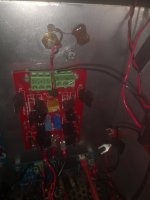
The cascode on the positive rail appears to be unstable. Here is a photo of the board in place. The drop across the cascode is the same on either rail. 30 volt rail => cascode is just under 8 volts.
When measuring the gate voltage, zero is expected for either polarity and zero is measured. If I know push on the PG+ connector with the probe, the measurement jumps to rail voltage.
I assume that a circuit opens with the smallest deflection of the board on the cascode.
Does this mean that the base of the cascode resistor is at zero when reading rail voltage? I have taken the heatsinks off the cascode to get the grabber on to the emitter.
Attachments
Last edited:
Sheesh, it's been a long time away.... Vgs is gate to source voltage. Source is rail, so gate needs to be near rail prior to biasing.
The issue may have been a poor solder connection to the terminal block. The $15 dollar store iron did a great job fixing it.
Tested the connection by screwing in a wire and measuring resistance through the wire to collector of cascode transistor. This might have worked before soldering as well.
It looks like you can only trust a terminal block when it's jaws are under tension.
Last edited:
I've started biasing. 5 meters, 4 across the board test points, one across the speaker outputs. Input is shorted. Thanks to dazed2 for lending me 3. The good news is that all 4 meters agree.
The bad news is that I cannot zero the DC offset once the bias gets to 110mV. The pot controlling the negative side stops doing anything -- I guess it is maxed out.
Powered down and measuring across the test points on the front end board shows 666 ohms on the positive and 752 on the negative side.
The 1K resistor is 1% PRP. I have a few more 100 ohm PRP resistors, a pair of 330 I could wire in series....
Is there anything to check before increasing R6 ( 1k )? Does R5 also need to change? What value is recommended?
The outputs are IRFP240 and 9420.
- Home
- Amplifiers
- Pass Labs
- F5 Turbo Builders Thread