no.
using a 35Vac transformer you will likely get ~50Vdc to 51Vdc across the smoothing caps when mains voltage is nominally the same as the transformer rated voltage. Use 63V capacitors, not 50V.
The supply voltage will droop when you bias the amplifier.
Expect the droop to be about 2Vdc when passing 1A of bias and 3 to 4 volts when passing 2A of bias. For 100W into 8r0 the bias will need to be almost 2.6A and the likely supply droop will be around 4 to 5volts.
That will bring your rail voltage down into the range 46Vdc to 48Vdc.
This should be just about enough to ensure you get 40Vpk into your 8r0 dummy load.
Now your output stage is dissipating ~244W (94V * 2.6A) and will need big heatsinks.
He should use 30 volt transformer...
I guess that would still be enough for F5 amp

I still remember the times when 33V trafo was 'big', and close to the classAB 'safe limit' with any DIY amp

and now in classA...DIY certainly have changed
Buy the spec'd 24V secondary trafo that Nelson recommends in the article. It will yield correct rail voltage(appx 32v) to take advantage of current avialable from output, set according to the article. Venture outside these lines and you must realize that you are on your own and need some level of understanding to finish the build. You must also consider that at greater voltages, dissipation becomes a major issue, even if you have big sinks, as the fets will be operating at a high level, despite what the sinks are able to do in getting rid of that heat. In my opinion, If you want higher voltage, you must begin to increse the amount of output pairs in order to bring down the individual temperature of the fets. Then the focus is again shifted to the sinks and their ability to dissipate heat.
The F5T V3 is a beast of an amp. There are speakers that need more, but i would venture to suggest biammping or buying some Pass Labs products.
The F5T V3 is a beast of an amp. There are speakers that need more, but i would venture to suggest biammping or buying some Pass Labs products.
AndrewT,
I heard NP says to use 1.3 as the multiplier instead of 1.414 when calculating the expected rail voltage when for a class A amp. Then, 36 VAC secondaries make for 46.8 rails, with the bias droop built in. That agrees very closely with your observation. It will have no trouble making 100 watts.
The 1.3 multiplier makes 30 VAC become 39 volts, when accounting for droop, but that won't quite make 100 watts. Close enough maybe? Only dazed2 can say.
I am missing something here. Perhaps someone can help.
Suppose Prms = 100 watts into 8R0 -- pure resistive so that the current and voltage are in phase.
Then,
Prms = I^2 * R => I^2 = 100/8 = 12.5
so, I = 3.54 amps RMS
Then, Vrms = I*R => 3.54 * 8 = 28.28 volts RMS
(check P=IV =3.54*28.28 = 100 )
Let Vrms = Vsec -- the transformer secondary.
Now, Vrail = Vsec * 1.414 = 40 VDC (the peak voltage)
Using a factor of 1.3 instead of 1.414 for losses due to class A biasing, means to achieve a 40 VDC rail, you need a 40/1.3 VAC transformer => 30.75 VAC.
This suggests that 100 watts RMS is possible from a 30.75 VAC transformer.... but that's not right, is it?
Can someone please point out where I blew it?
Last edited:

go and look at the F5 pdf.I am missing something here. ..........................
Can someone please point out where I blew it?
It states a +-25Vdc supply and yet the maximum output is ~20Vpk
That difference (or loss) is due to current passing through the semiconductors and actual resistances, from supply to the terminals and then back to the supply.
The same applies to all amplifiers.
Thanks AndrewT.
So, for 40 Vpk loaded, we need 45 Vpk unloaded, or a theoretical 45/1.414 = 31.82, or about 32 VAC for 100 watts RMS into 8R0 when biasing at around 2.6 amps. Using 1.3 instead of 1.414 as the rectification constant, gives us a 35 VAC transformer.
If the rule of thumb for PS droop is about 2 volts/amp/pair of transistors, then for a large number of output transistors, say 4 pairs, each biased at 1 amp, we should get an 8 Volt droop or so.
That means to get 40 Vpk from 4 pairs becomes 48 Vpk, which needs a theoretical 48/1.414= 34 VAC transformer. Using 1.3, gives a 37 VAC transformer. A 36 VAC transformer ought to be close to the the right size for a 100 watt amp using 4 pairs of outputs biased at 1 amp.
Higher bias means more droop, so if the 4 pairs are biased at 1.3 amps, the droop will be closer to 10 volts, which will need 50 Vpk, or between a 36 and 38.5 VAC transformer. That makes a 38 VAC transformer the better choice.
That is much more clear. thank you!
Thanks!
The interesting thing about this is that you can use a lower voltage transformer with fewer pairs, but still acheive the 100 watts output. I'm guessing that fewer pairs means more clarity, while more pairs means higher damping factor and better longevity.
Last edited:
That's back to front................The interesting thing about this is that you can use a lower voltage transformer with fewer pairs, but still acheive the 100 watts output. ..........
The losses should be lower as the number of output pairs is increased.
Select your idle output bias as 2.6A.
That allows for 5Apk of ClassA output into 8r0.
A single pair would need to be biased to 2.6A. The losses will be the sum of the cable resistance losses + the trace losses + the emitter resistor losses + the return cable losses. While still in ClassA the PSU will suffer virtually no droop from the fully biased voltage.
A dual pair would have each pair biased to 1.3A. The losses through each pair carrying the half current halved. Those wires carrying the full 5Apk would not be any different from the single pair case.
A 3pair would have each pair biased to 867mA. The losses are divided by 3
A 4pair etc.....
A 6pair etc.....
yet another unhelpful post?
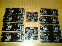
just started my F5 turbo V3 build. the PCB's i'm using is toecutter's prototype V3 boards. wich i cut in half(output boards that is) to get the heat spread well over my 2x10.080" profiles.
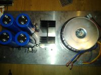
got the PSU layout ready to night. 1000VA 2x40V transformer 2x35A rectifier bridges(on there own sink). and 4x68.000uF caps. softstart will be modified hypex.
this is ofcourse monoblocks
got the PSU layout ready to night. 1000VA 2x40V transformer 2x35A rectifier bridges(on there own sink). and 4x68.000uF caps. softstart will be modified hypex.
this is ofcourse monoblocks
Attachments
Last edited:
That's back to front.
The losses should be lower as the number of output pairs is increased.
Select your idle output bias as 2.6A.
That allows for 5Apk of ClassA output into 8r0.
A single pair would need to be biased to 2.6A. The losses will be the sum of the cable resistance losses + the trace losses + the emitter resistor losses + the return cable losses. While still in ClassA the PSU will suffer virtually no droop from the fully biased voltage.
A dual pair would have each pair biased to 1.3A. The losses through each pair carrying the half current halved. Those wires carrying the full 5Apk would not be any different from the single pair case.
A 3pair would have each pair biased to 867mA. The losses are divided by 3
A 4pair etc.....
A 6pair etc.....
yet another unhelpful post?
Actually, it is helpful. 4 pair gets biased to 2.6/4 = .65 ma.
Since the losses are related to the bias current, lower bias => lower losses, in my example, as the bias was not decreased as extra pairs were added, there was a lot of added droop.
But, since the bias goes down with more pairs, as do the losses, then the size of the power transformer will also go down as pairs are added.
Are we suggesting that as the voltage droop is a MAX of 5 volts or so, then the actual droop = 5* 1/number_of_pairs?
eg, With two pairs the droop is halved, three it is a third, 4 it is a quarter? ie, with 4 pairs, the droop is not 5 volts, but only 1.25?
That would mean that a 4 pair amp putting out 100 watts rms into 8R0 would need to make only 41.25 Vpk to cover the looses, which gives about a 32 VAC transformer. (Using 1.3 as the rectification constant.)
With 36 VAC * 1.3 = 46.8 Vpk, or about 45.55 Vrail after losses for 4 pairs yields close to 130 watts RMS Class A power, biased at just 0.65ma.
Do I have it right now? The more pairs, the less losses, the more output power.
I hope this is not like banging your head against a wall -- I'm trying to learn that rule to select the right transformer, without someone just saying use XX vac...
Thanks for helping.
- Home
- Amplifiers
- Pass Labs
- F5 Turbo Builders Thread