as i always say. build it right the first time")
I don't think anyone starts building an amp with an objective not to build it right ;-) Errors do creep up in different forms including component failures and spurious copies.
Audiosan,
Thank you so much. Your observations are always so astute. I on the other hand have screwed up on construction projects everyway possible. It has helped me learn how to fix things. Try this, unhook the board from the heatsink, using a variac bring the power up slowly and carefully, to around 8 or 10 volts output on the power supply. Feel the output transistors. If only one side +/-, gets warm, you can test the transistors on the other side. If they test fine start looking at the resistors.
Thank you so much. Your observations are always so astute. I on the other hand have screwed up on construction projects everyway possible. It has helped me learn how to fix things. Try this, unhook the board from the heatsink, using a variac bring the power up slowly and carefully, to around 8 or 10 volts output on the power supply. Feel the output transistors. If only one side +/-, gets warm, you can test the transistors on the other side. If they test fine start looking at the resistors.
Wired up a new PCB and component set for the bad channel. Works perfectly well now. Biases nicely and stable. Took it upto 350mV bias. The heatsinks are massive and very effective. Originally over engineered for Turbo V3. They get to be mildly hot.OK, got the board that was giving problems (left channel), wired up again after fixing few dry solders and a loose connection at middle leg of P3.
Board biased nicely. Took it up to 200mV bias and let it settle. Then connected the speaker and played music. Seems to play well and without any gain issues, previously encountered, but I could hear distortion a little bit, compared to the other channel (right channel) which is playing music brilliantly like with any Pass amp, no distortion and full dynamics.
Tried taking the problem channel (left) to bias around 350 mV. That's when I realized there is a problem. The trimmer P1 maxed out and could not push the bias anymore than 320 mA. Then twiddled around with P3 and there seems to be a big impact on output null and the bias levels. Altered a little bit of P3 and managed to set the bias to 350mA. Connected music and played - same problem as earlier case. No gain. Very feeble. Then turned the P3 the other way and connected, while monitoring the bias. Music played back normally (with little bit of distortion) and in a short while, smoke came out from 2SK170. Quickly disconnected the power and removed the board to examine. 2SK170 split open near the base of it's legs. I suspect the P channel MOSFETs are also gone. Luckily the speaker is a test one and nothing happened to it.
Any insights what could have happened? May be it's a bad P3 component. Rest of the components are checked. Seem OK.
I will park this board for a while to debug in leisure. I cannot afford blown MOSFETs. I have a spare PCB. Will stuff it up, double checking this time with presets and everything else.
Cheers.
Checked the audio. Works perfectly. Did not listen enough to find the differences between my existing F5 builds and this. Looks like I have completed the build of F5 Turbo V2. Will post pictures once I tidy up the wiring in a day or so.
Thanks to everyone for their help.
Cheers.
Awesome. I would like a impression based on direct comparison with regular F5. You may be one of few that has both on hand to compare.
Thanks. I will compare both and post my impressions. BTW the mosfets and the diodes are from you ;-) Thanks for the help to the DIY community. My next one in a identical chassis is the V3. But for the screw-up w.r.t to mounting holes on the heatsink for the mosfets, I would have gone into the testing phase of V3 as well.
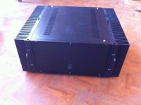
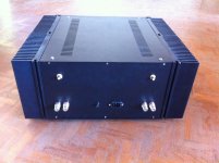
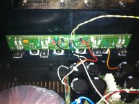
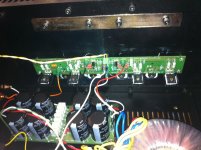
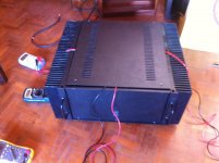
Pictures of completed F5 Turbo V2
As mentioned in an earlier post, completed the build including setting up the biases, monitoring heat and stability etc.
Also did few hours of sound testing with my Fostex back loaded horns, which are currently used with a standard F5.
As far as impressions of the sound are concerned, the amp is simply outstanding. It has F5 like detail and clarity and has very strong dynamics and a solid bass support. Each and every instrument can be felt and heard. The amp does not attract attention and one instantly starts enjoying the music rather than hearing the amp. There is no fatigue. The difference between a regular F5 and F5 Turbo V2 as far as my build comparison is concerned, is that the Turbo is bit more warmer and more in control. It has stronger dynamics and support for stronger bass. These needs to be taken as a relative comparison and in no way a comment on standard F5's sound. While the sound signatures are almost similar, I should be able to tell a Turbo in a blind test due to stronger dynamics and bass.
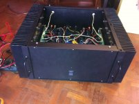
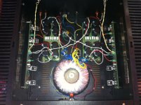
Definitely a keep in my collection. Have a minor non-instrusive hum problem to be resolved in terms of double ground from my preamp. Also have a suspicion that 8 x 10000 uF per power supply rail is not sufficient enough. It probably needs to be 8 x 22000 uF. With higher bias, the capacitors are adding leakage current.
The heatsinks are warm and not hot enough. The Toroid is a 1KVA model. Both these are a overkill for a V2. Will use the trafo for V3 soon and swap it with a 600VA model.
Here are the pictures:
As mentioned in an earlier post, completed the build including setting up the biases, monitoring heat and stability etc.
Also did few hours of sound testing with my Fostex back loaded horns, which are currently used with a standard F5.
As far as impressions of the sound are concerned, the amp is simply outstanding. It has F5 like detail and clarity and has very strong dynamics and a solid bass support. Each and every instrument can be felt and heard. The amp does not attract attention and one instantly starts enjoying the music rather than hearing the amp. There is no fatigue. The difference between a regular F5 and F5 Turbo V2 as far as my build comparison is concerned, is that the Turbo is bit more warmer and more in control. It has stronger dynamics and support for stronger bass. These needs to be taken as a relative comparison and in no way a comment on standard F5's sound. While the sound signatures are almost similar, I should be able to tell a Turbo in a blind test due to stronger dynamics and bass.
Definitely a keep in my collection. Have a minor non-instrusive hum problem to be resolved in terms of double ground from my preamp. Also have a suspicion that 8 x 10000 uF per power supply rail is not sufficient enough. It probably needs to be 8 x 22000 uF. With higher bias, the capacitors are adding leakage current.
The heatsinks are warm and not hot enough. The Toroid is a 1KVA model. Both these are a overkill for a V2. Will use the trafo for V3 soon and swap it with a 600VA model.
Here are the pictures:
Attachments
Anivila, great job!
Thank you for the review of your impressions against the F5. What you said is exactly the reason I am about to embark on building the V3
BTW how did you go about tuning harmonics using P3?
I did not tune the harmonics yet. The wiper of 200 ohms preset is set in the middle. I don't have the means to measure distortion nor do I have access to scope. Will attempt one of these days, if I can do it with a borrowed scope.
what's the sec voltage for that 1KVA transformer?
The secondary voltage of the toroid is 24v per winding.
I completely missed this fact. I agree. I might get higher current capability with more number of output devices but there will be no higher voltage swing. Looks like I need to order a 35V secondary trafo for V3.2x24V transformer is useless for V3. you vill not get any more power from it, then from V2.
you need about 2x35V transformer to hit the magic 100W class A number at 8ohms.
Testing harmonic structure means buying a soundcard and getting free software like ARTA or Visual Audio analyser. Audio San is correct that you would have plenty of available CLass A current, but would be voltage limited.
I do have decent sound cards including an external USB M-Audio device. I need to check on the software.
2x24V transformer is useless for V3. you vill not get any more power from it, then from V2.
you need about 2x35V transformer to hit the magic 100W class A number at 8ohms.
Lol ,
magic 100watt
what makes 100 watt @8 ohm magic .....?Just did some quick calculation. Please tell me if I'm wrong.
at 100W into 8 ohm you will need 26.83VDC at the speakers. Since we need to calculate it in ACV then we multiply by root 2 or 1.414 thus giving us about 40V rails.
Using NP's approximation 40V rails would require about 30V secondaries at the transformer.
Is this correct?
at 100W into 8 ohm you will need 26.83VDC at the speakers. Since we need to calculate it in ACV then we multiply by root 2 or 1.414 thus giving us about 40V rails.
Using NP's approximation 40V rails would require about 30V secondaries at the transformer.
Is this correct?
- Home
- Amplifiers
- Pass Labs
- F5 Turbo Builders Thread