It's only the Jfets you need to worry about being faked but both jfets and mosfets need to be matched. The IRF mosfets are easy to get and not faked but if you order them from a supplier you will need to match them yourself.
For the Jfets all parts need to be matched (N parts to P parts).
For the mosfets the N parts do not need to match the P parts but each channels P parts need to match. The parts do not need to be matched channel to channel but it's better. The matching is done so that a single mosfet of each channel doesn't "bias hog" and get more current and thermally run away. Ensuring the all the positive and negative mosfets on each channel are the same makes sure this doesn't happen.
Member NicMac has both genuine Jfets and Mosfets:
http://www.diyaudio.com/forums/members/nicmac.html
Or DIYaudio store although they are out of stock on the Jfets now:
The diyAudio Store - DIY amplifier kits, chassis, and parts
Matching Jfets:
Matching Jfets
Post #3, Take care of polarity with the battery...
Matching mosfets:
http://www.firstwatt.com/pdf/art_matching.pdf
These tests will also tell you if your devices are bad.
Doing all this is quite a lot of work and I am guessing Jim's Audio probably doesn't do it at the price they sell the kits for. Also, you see the Jfets alone (matched) are $50.
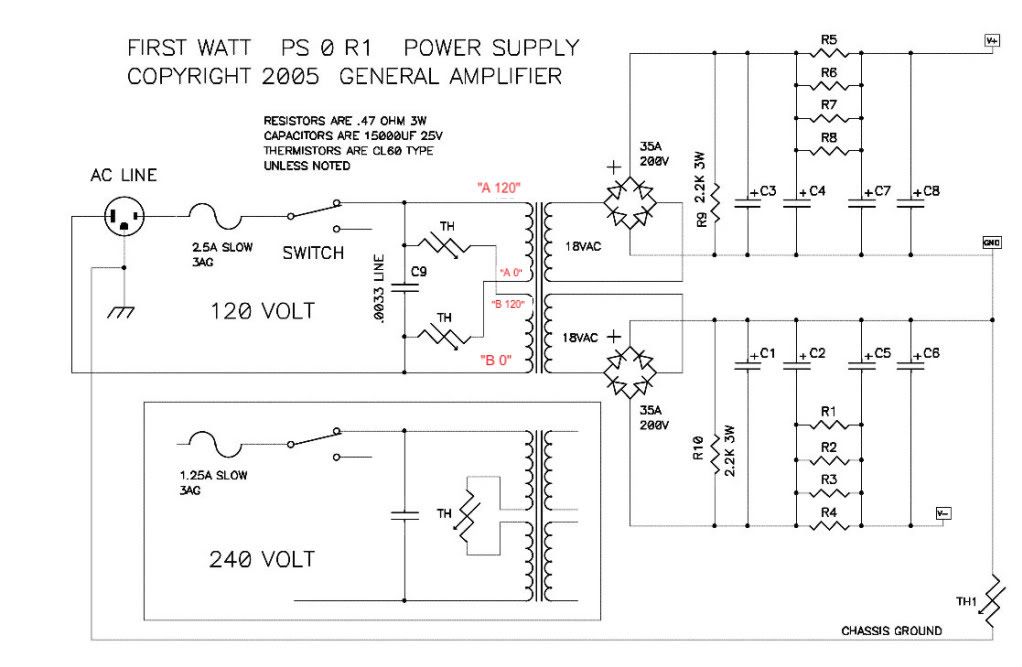
thank you a lot, hikari! the problem was in universal PSU PSB (photo included). I think they are for 120V (USA). Im from Europe, so I used one 230V 500VA transformer with two separate secondary 18V output. no common middle point on transformer secondaries. so I has a two separate diode bridges (40A100V shootky, 4 pieces per channe).
I tested PSU separately for each channel and all was good, 18V input, near 22-24V output. But my mistake was that I didnt tested PSU when two secondaries are connected to PCB. Think the scheme of PSU is just doubled output voltage on each channel.
After I figure out this, I make deleted with knife the common point from PSU PCB) and made two fully separate channels and output voltage was OK about 22-24V. then connected it again to amp and chassis. But maybe my ground was made with mistakes. inputs RCA and outputs ground was connected directly to chassis, maybe this was the problem...
Imgur: The magic of the Internet
stop what ever you are doing before you kill yourself.
anyway, I need to finish it
")
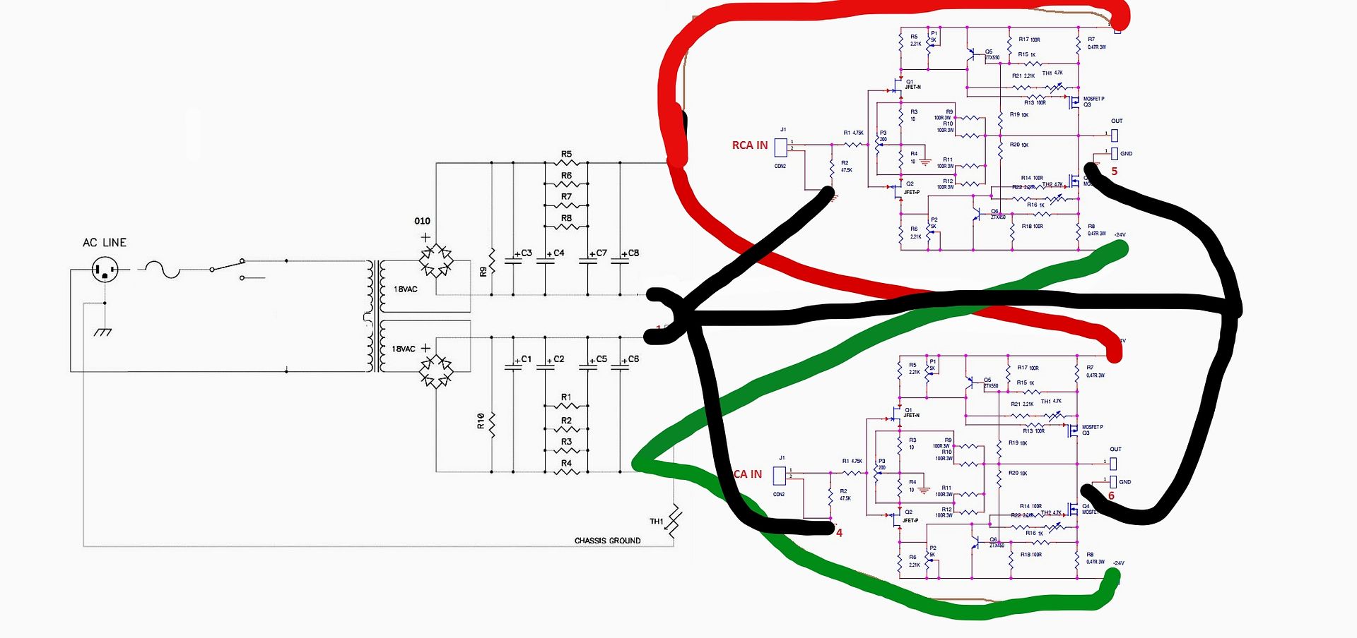
make a scheme of amp, can anybody help me with ground connections?
An externally hosted image should be here but it was not working when we last tested it.

I saw this, but I cant figure out if the and GND point needs to be connected (1 and 2 on my scheme) near C6 and C8. when I connected it the voltage was doubled.
I guess point 3 and point 4 (inputs grounds from RCAs) needs to be connected, right? but what to connect to output speaker grounds 5 and 6 ?
Do I need common grounds between two independent PSU rails?
I guess point 3 and point 4 (inputs grounds from RCAs) needs to be connected, right? but what to connect to output speaker grounds 5 and 6 ?
Do I need common grounds between two independent PSU rails?
Also know that the Jim's Audio PCB were made without permission and generally we ignore calls for assistance when people use these boards.
That said, get your connections right, and then start replacing the components you smoked when you hooked up the amp boards with the too-high voltage.
That said, get your connections right, and then start replacing the components you smoked when you hooked up the amp boards with the too-high voltage.
Also know that the Jim's Audio PCB were made without permission and generally we ignore calls for assistance when people use these boards.
didnt know that. where I get get "official" PCBs?
photos
An externally hosted image should be here but it was not working when we last tested it.
An externally hosted image should be here but it was not working when we last tested it.
An externally hosted image should be here but it was not working when we last tested it.
Sorry for having to use online photo editor.
I did like that at first time, and the voltage was doubled from 20V to 40V. I think thats because for serial connection of +leg C6 cap and -leg of C8.
What voltage I need after diode bridges?
Last edited:
the railvoltage is +/-23 Vdc. if you measure from + to - you will see 46Vdc. that is correct.
even for simple F5 not turbo?
those numbers are only for standar F5. F5turbo v1 and v2 is +/-32Vdc and v3 is +/-47ish Vdc.
so its OK?
rails — imgbb.com
An externally hosted image should be here but it was not working when we last tested it.
thanks for all replies. maybe I will buy dozens of cheap fake Jfet just for future fire up tests
still cant understand, why we need serial connection between two rails on grounds (two CRC filters).
and also, what function of TH termistor (CL-60 or NTC10 I have)? Just to break up loop between safety earth ground and audio input-ouptut grounds?
still cant understand, why we need serial connection between two rails on grounds (two CRC filters).
and also, what function of TH termistor (CL-60 or NTC10 I have)? Just to break up loop between safety earth ground and audio input-ouptut grounds?
- Home
- Amplifiers
- Pass Labs
- F5 Turbo Builders Thread