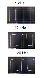
1 kHz (amp)seems to be good.have you checked for overshoot on a 1kHz squarewave?
I shall check my ba-3 frontend.
Attachments
How much power from a V2Cascode?
Hi folks
I recently built an Aleph J and it sounds great. I would also like to build a higher wattage F5. I am wondering how much power can be had from a V2 cascode built in mono block format in a pair of cases each with about 10% more heat sink than the standard 4U store case.
I would like to get 80-100w at 8 ohms. Than means running 40-44v supply rails and perhaps .65a bias/fet for 26-29w dissipation/fet.
I'm not looking to drive 2 ohm loads with the amp or generate large amounts of class A power.
That much heat sink should be able to take the 60w /side of dissipation but can the output stage of a V2 do the job. I'm thinking that the power supply should be sized to limit the continuous power output to a safe level. Perhaps a 400w toroid? The class a bias dissipation would be 120w/ch so 400w would be 3x the bias power. Any guidance would be appreciated.
Last edited:
Perhaps I'm out of my depth here but you might be looking in the wrong direction.
Because P=IV and you double the current requirements going from 8 to 4 Ohm and again at 2 Ohm you really need to look at a design with a bunch of output devices and not at something that swings a lot of voltage. Look into the Burning Amp configurations and perhaps into a set of 5U cases.
Because P=IV and you double the current requirements going from 8 to 4 Ohm and again at 2 Ohm you really need to look at a design with a bunch of output devices and not at something that swings a lot of voltage. Look into the Burning Amp configurations and perhaps into a set of 5U cases.
Your math is mostly correct, the biggest thing I'd suggest is more devices and less standing bias, you don't want the turbo diodes conducting at idle.
Basically, build a V3, especially as you have 2 cases and can make monoblocks. That would work well.
Your limits to continuous power will always be clipping, so undersizing the PSU is not really suggested.
Also, for higher power options, look at the BA-3 balanced. With the power supply you suggest it would be loafing at 100WPC.
I think PSU limiting is the wrong way to go. Although some guitar amp manufacturers do this, they are operating in class AB at best. With Class A, or heavily biased AB as you seem to be targeting, there is always a lot of current flowing in the transformer. This generates heat, and an undersized transformer will generate more heat than a properly oversized/derated transformer.
Also, with the typical high capacitance filters we build, the power factor is low. My AJ is biased to about 180W (V x I) but my APC power conditioner says it's drawing 300 VA. Yet another reason to go massively oversized. Remember that transformers are rated in VA, so the only time that power rating equals watts is into a pure resistive load. My AJ has two 400 VA transformers (dual mono) and my upcoming F5T v2.5 has a pair of 500 VA transformers.
How best to limit output power? Gain structure if you are worried about someone else cranking the volume knob too high, just set the gain structure of your system so that the loudest position of the volume knob results in acceptable power.
What I'm calling F5T v2.5 is essentially what you are targeting. The front end is cascoded, but I'm only using a single set of 2 pairs of outputs although I am planning only ~37V rails. I'm putting it in the 5U case. This makes packaging easier, although the 4U case will handle your 60W per channel.
Good luck with your build.
I think PSU limiting is the wrong way to go. Although some guitar amp manufacturers do this, they are operating in class AB at best. With Class A, or heavily biased AB as you seem to be targeting, there is always a lot of current flowing in the transformer. This generates heat, and an undersized transformer will generate more heat than a properly oversized/derated transformer.
Also, with the typical high capacitance filters we build, the power factor is low. My AJ is biased to about 180W (V x I) but my APC power conditioner says it's drawing 300 VA. Yet another reason to go massively oversized. Remember that transformers are rated in VA, so the only time that power rating equals watts is into a pure resistive load. My AJ has two 400 VA transformers (dual mono) and my upcoming F5T v2.5 has a pair of 500 VA transformers.
How best to limit output power? Gain structure if you are worried about someone else cranking the volume knob too high, just set the gain structure of your system so that the loudest position of the volume knob results in acceptable power.
What I'm calling F5T v2.5 is essentially what you are targeting. The front end is cascoded, but I'm only using a single set of 2 pairs of outputs although I am planning only ~37V rails. I'm putting it in the 5U case. This makes packaging easier, although the 4U case will handle your 60W per channel.
Good luck with your build.
Thanks for the input Bob
I don't think a 400va transformer will be limited in this situation the same way a guitar amp would be since the guitar amp is designed to clip during normal operation to get a certain sound. The way I look at it is total power available - power output to speakers= max power dissipated by the output stage and rectifiers, resistors etc. So, by limiting the power available it would limit the continuous dissipation in the output stage while still allowing peaks. 400w is 3 times the continuous bias figure which is what Mr Pass recommends. I completely understand the desire to overbuild but I want to keep the amps as light and as reasonably priced as I can while still achieving the power level I want.
It's interesting that in pro audio applications the rule of thumb for average power output in an amp driven just to the point of clipping with typical program material is 10%. For hard clipped max. volume it's 30%. So in practice I am not likely to run into the limits with actual program material, particularly with 8ohm speakers.
Power factor is definitely a consideration. When I built my Aleph J I used a choke input supply. The power readings were 186w and 206va = .90 which is a very good power factor. Unfortunately the chokes hummed like crazy in a choke input setup even though they were rated for 12 amps. I bought a new 400w Antek transformer, changed to CLC and the power factor went down. The readings are now 220w and 300va with a 115v line voltage. The increase in watts is mostly due to a higher bias current setting and a higher +- dc voltage. Power factor is now .73 which is pretty typical for a cap input supply. The 400w transformer runs pretty warm but not hot, although I don't think I would push it much past that level for continuous duty.
I'm very interested in your build of F5T V2.5. With 37v supplies you would be close to the 80w or so that I want. The 5u case is big but it would seem a challenge to fit 2 dual mono 500w power supplies in there. I like the idea of using one case because it would keep the FE and output boards on the same side of the chassis. Since I am in Canada shipping and duty and dollar exchange add a huge premium to the cost of the store chassis. I'm looking at 2 smaller chassis on eBay for my build. I'm still trying to decide how far up the F5T ladder to go. Your input is appreciated. I'll be watching for a build thread on your F5T v2.5
Last edited:
At least with Antek, there's only a $10/100 VA premium to go bigger. I figured it was cheap insurance against excessive heating. I tend to have my system on most of the day, so I err on the side of caution. You also get a bit higher rails than usually predicted based on secondary voltage. My A-J has 25V rails loaded out of 20V rated transformers.
1 kHz (amp)seems to be good.
I shall check my ba-3 frontend.
I found the sound i was looking for, it matched my speaker very well.
It's a nice clear and warm sound.
I cranked up the bias around 0.42v around the source resistor on the F5 t v1.
On my ba-3 frontend i put an extra capacistor C4 16nF (lowpass filter).
It did the sound mutch smooter with my speakers.
It sounds really good before the upgrade, but the high tones could sound litte metallic.

Attachments
the 332r||16nF is a very difficult load for the amplifier.
The amp is having to work very hard ebven without an attached Receiver & cable.
There must be a better way than what you have ended up with.
It's trial and error for me.
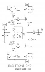
The schematic i used for the ba-3 peamp is this (picture)
Any other idea about hot to make a better lowpassfilter for the ba-3?
Attachments
The proponents of keep it simple have us believing that missing things out is better than including necessary components.
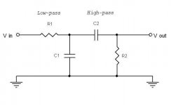
The input to an amplifier needs in my view two passive filters to define the passband.
The simple sch does not include any filters.
The designer and others tell us that the capacitance of the jFETs act as the necessary RF attenuation filter. I don't believe them !
Adding a fixed capacitor (rather than a variable capacitance at the jFETs) after the R1 input resistor and in parallel to R2 fixes the RF attenuation.
Andrew
IMHO it would make things much clearer to very many builders if you posted an amended circuit with your additions and component values.
Many builders can not calculated these things but are capable of following a diagram.
Just posting comments against the existing circuit without giving details that ordinary builders can follow does not help people.
The proponents of keep it simple have us believing that missing things out is better than including necessary components.
The input to an amplifier needs in my view two passive filters to define the passband.
The simple sch does not include any filters.
The designer and others tell us that the capacitance of the jFETs act as the necessary RF attenuation filter. I don't believe them !
Adding a fixed capacitor (rather than a variable capacitance at the jFETs) after the R1 input resistor and in parallel to R2 fixes the RF attenuation.
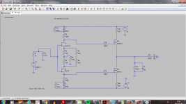
Something like this? (picture)
Attachments
Quick Question
Hello,
i build two F5 Monos, years ago. Sound good, no problems but Id like to have a little more ompf and decided to build F5T v2 Monos. My question is: How would you bias the Amp for Low Z speakers. I thought about lowering the Rails to 25V and increase the bias to lets say 2 Amps per transistor. The monos will be actively cooled, because it can help increase temperature stability and allows for a smaller enclosure. At 2 Amps and 25V each Transistor would see 50W Dissapation, do you think thats manageable?
I'm taking IRFP150N to 50W , but 240/9240 are wimpier
if there is any possibility - put more output pairs
in final , price of semis is not defining in entire project
Is there any readily available alternative to the 240/9240?
50W for IRFP240/9240 is pretty high and I guess the standard PCB set contains
only two pairs of devices per channel.
If you're building mono blocks, have you considered using two sets of PCBs (so you
can build F5V3 mono blocks with 4 pairs of devices per channel) and then just
scale the design back to what you want?
Cheers,
Dennis
only two pairs of devices per channel.
If you're building mono blocks, have you considered using two sets of PCBs (so you
can build F5V3 mono blocks with 4 pairs of devices per channel) and then just
scale the design back to what you want?
Cheers,
Dennis
Is there any readily available alternative to the 240/9240?
I guess you're asking about parts with higher dissipation?
- Home
- Amplifiers
- Pass Labs
- F5 Turbo Builders Thread