added a 10ohm resistor like the picture above from bk856er
the noise is the same. 0.4mvac. ARTA shows equal results. do you think its time to give up on the ixys?
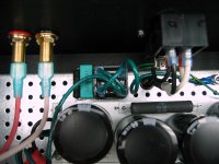
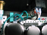
Can't comment on the ixys. Below is how I have the GLB wired up on my M2. Notch is at the lower right.
BK
Attachments
How things are now:
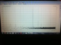
2mvac inputs shorted (after the rectifier bridge job)
50hz hum is -93db inputs shorted, however the 100hz noise is higher (-85db) i think this 100hz noise was there all this time. if i disconnect the amp from the soundcard, this 100hz noise disappears.
After this, i connected it to my speakers and cd player through rca. without playing any music, the hum was there like before but if i disconnect one rca @amp at a time, the hum goes almost completely away. with another source i have the same problem and if i switch interconnect cables the hum persists. I've been reading and it looks like a ground loop problem. don't know how to solve it. i will post pictures for you to see my Psu and amp connections.
thank you for your time and patience
An externally hosted image should be here but it was not working when we last tested it.
An externally hosted image should be here but it was not working when we last tested it.
An externally hosted image should be here but it was not working when we last tested it.
An externally hosted image should be here but it was not working when we last tested it.
An externally hosted image should be here but it was not working when we last tested it.
An externally hosted image should be here but it was not working when we last tested it.
Joca, be sure to check your diode bridge markings. I'm a paint by numbers guy and not a guru, but ESP cautions "Note the way the bridge is wired, with the two AC terminals shorted, and the two DC terminals shorted. Other connection possibilities are dangerous, and must be avoided." My bridge has a notch, yours does not. Terminal orientations seems to be different in our implementations. Safety first.
What does the yellow wire connect to on your PS?
Also, what is your toroid shield lead connected to? Some say to keep the lead length as short as possible and connect to chassis.
BK
What does the yellow wire connect to on your PS?
Also, what is your toroid shield lead connected to? Some say to keep the lead length as short as possible and connect to chassis.
BK
Joca, be sure to check your diode bridge markings. I'm a paint by numbers guy and not a guru, but ESP cautions "Note the way the bridge is wired, with the two AC terminals shorted, and the two DC terminals shorted. Other connection possibilities are dangerous, and must be avoided." My bridge has a notch, yours does not. Terminal orientations seems to be different in our implementations. Safety first.
What does the yellow wire connect to on your PS?
Also, what is your toroid shield lead connected to? Some say to keep the lead length as short as possible and connect to chassis.
BK
the noise bridge rectifier is properly connected.
my yellow wire goes to psu ground and is conected to the dc terminals in the bridge.
i have a nut and washer pressing the ac shunt. under this, i have the earth to chassis conection properly made.
noise when i connect the rca from source. if no rca connected=no noise, 2mvac
No................my toroid has an earth wire. i supose that i have to connect it directly to the mains earth. right?
The screen wire conducts high frequency and very high frequency and ultra high frequency and cell phone interference to chassis.
It can only do that if the impedance of the connection is ultra low.
The screen lead MUST be VERY SHORT.
Connect to Chassis where it comes out of the insulation. Maybe turn the toroid with the lead outs facing the floor panel to get this screening lead even shorter.
This tells me you have not read about nor implemented HBRR & HBRL.......................
After this, i connected it to my speakers and cd player through rca. without playing any music, the hum was there like before but if i disconnect one rca @amp at a time, the hum goes almost completely away...............
Read D.Joffe.
This tells me you have not read about nor implemented HBRR & HBRL.
Read D.Joffe.
This tells me you have not read about nor implemented HBRR & HBRL.
Read D.Joffe.
And you are right! I didn't! Thank you for the info on that. Lately i've been reading more than sleeping!

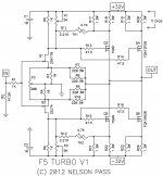
Playing around with my f5 turbo v1.
It sounds pretty good with my Carbon 7se speakers.
The bass and middle register is great, but high frequency ex, disted guitar is little to sharp for my taste, want little warmer high tones,
First i adjust the P3 control for minimal distortion, and after that raised the second harmoic.
se picture (ba-3 f5).
The feedback resistors R7 through R10 have been increased to 220 ohm, and the feedback is less -7 dB, if i understand it correct.
Can i increase the r3 and r4 from 10 to 22 to get little less feedback and get little
warmer sound?
I try to learn, so have a little patience,")
It sounds pretty good with my Carbon 7se speakers.
The bass and middle register is great, but high frequency ex, disted guitar is little to sharp for my taste, want little warmer high tones,
First i adjust the P3 control for minimal distortion, and after that raised the second harmoic.
se picture (ba-3 f5).
The feedback resistors R7 through R10 have been increased to 220 ohm, and the feedback is less -7 dB, if i understand it correct.
Can i increase the r3 and r4 from 10 to 22 to get little less feedback and get little
warmer sound?
I try to learn, so have a little patience,
Attachments
Last edited:
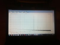
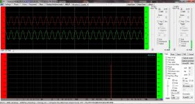
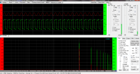
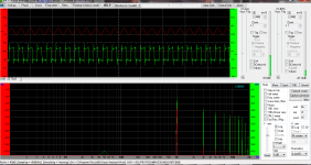
I checked the output waves, i think it looked okej.
I did a loop from the soundcard and compared the the waves from the amp.
The amp sounds wonderful.
But i want to tweak the sound little for my music preference.
I read "Increase feedback resistors R9-12 to 200R and source resistors R3/R4 to 20R (R1 schematic). It will produce a warmer sound as well as increase output volume"
Nelson: "The F5 is right on the edge of what of how much feedback you can use
without compensation capacitors. Reducing the feedback on it won't
hurt it at all."
I use 32v rail and have already 220 ohm resistor, can i just try to switch from 10R to 20R (R3/R4)
without damage?
Have any one tried this mode?
How does it sounds compare to the original?
Attachments
increasing the 10r source resistors to 20r has at least two effects I am aware of.
a.) the current through the jFETs reduces to somewhere between 50 and 60% of the value when 10r is used.
b.) the gain of the amplifier goes down. This increases the feedback.
Both of these could cause serious performance consequences.
It would be better to alter the gain upwards by increasing the 220r (upper leg of the NFB). This reduces the feedback and the amplifier becomes less likely to overshoot, ring, oscillate.
I suggest two modifcations to the standard build.
c.) Add a proper RF attenuation filter to the input. Set it somewhere between 50kHz and 300kHz. Lots of leeway to suit preferences.
d.) Split the two 220r in parallel to series connected feedback resistors 3off 36r (3W) (=108r) would in my opinion offer the chance of better performance than 220r||220r (110r), due to less heating effect and less voltage effect. You could even go to 4off 27r (2W) in series (also 108r equivalent).
4off 30r (2W) would reduce the feedback slightly.
Last edited:
Thanks for the input.
it's a lot to take in for a newbie
Do you recommend any good RF attenuation filter.
I have the cascade f5 turbo v1 with 32v rail, Nelson talked about
The first picture is from the soundcard next from the amp.
it's a lot to take in for a newbie
Do you recommend any good RF attenuation filter.
I have the cascade f5 turbo v1 with 32v rail, Nelson talked about
But it safe to put the resistor R7/R10 in serie?You may also notice that the feedback resistors R7 through R10 have been
increased, increasing the amplifier's gain to about 22 dB and decreasing the
amount of feedback by about 7 dB. If we are going to put out more power it is
appropriate to have some more gain, and it gives us more margin for
feedback stability
The first picture is from the soundcard next from the amp.
Attachments
R7 & R8 in series
R9 & R10 in series.
You need to change the values so that the combination gives the same resistance of the 110r equivalent of the 220||220
Okej, i got it.
Thanks for the help.
Last edited:

The mains fuse should be close rated, not the usual 3times larger to tolerate the transformer start up.Hello guys.
I planning to build a F5 next year.
but my question applies here too, I'm curious why the F5 doesn't have any fuses to protect the power supply and/or transformer?
do you guys put speaker dc protection?
thanks
If you are using a 400VA 115Vac transformer then fit a T4A fuse and add a soft start to prevent that fuse rupturing during repeated cold start ups.
If you value your speakers, then add some form of DC detection and alarm, or isolation, or shut down.
And if you build a DC coupled amplifier, then I recommend adding in a DC blocking capacitor to the source output.
- Home
- Amplifiers
- Pass Labs
- F5 Turbo Builders Thread