Hi Guys,
Once I had configured the amp on the bench as descriped above, I have out it aside for a while now as I needed to fix some speaker issues first (Fountek ribbons: laque got rotten, so each of my 24 ribbon tweeter needed to be dis-assemable, cleaned and assembled again...took a while).
So, today Iwanted to connect it first time on a speaker...ok, so this is what I did:
- cut away the signal to ground - brigde from the input (which I have soldered in when setting the bias)
- connected my tube-dac (BIII with unbalancer-output stage from broskie) instead
- first no speaker connected to be sure that I will warm it up first and measure output speaker voltage before I destroy any thing on my speaker.
- waited for an hour warm up, measured speaker out-pu voltage and got....
......2 V !!!!!! on both channels !!!!
it seems that the tube output stage introduces 150 mV DC btw, which in theory as well cant be the case as there is a coupling cap between the cathode-output and the input of the F5 as you can see here :
http://www.tubecad.com/2011/03/blog0203.htm
So, what happened here ? did I destroy the input stage of the F5? I am not brave enough to just plug in the speaker onto the amp with 2 V bias...
Last edited:
be polite and power up just F5 as separate unit , then measure output offset
try with input grounded , then non-grounded
then inform us
try with input grounded , then non-grounded
then inform us
Sure, never intended not to be polite, I was just shocked for a moment...sorry for that.
So, here you go:
- when I isolate the amp and short the inputs to ground, I have the same nice DC-behavior on the output as before (phuuuuu!!), so about 30-40mV Dc which goes down when warming up.
- when I let the input open (so, nothing on input and output), I get 2,7V DC on both channels, so I guess when warming up, it will go down to 2V as measured with the DAC connected to it before.
Does this makes sense ?
Thx for your help !
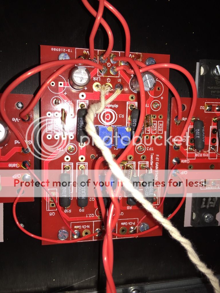
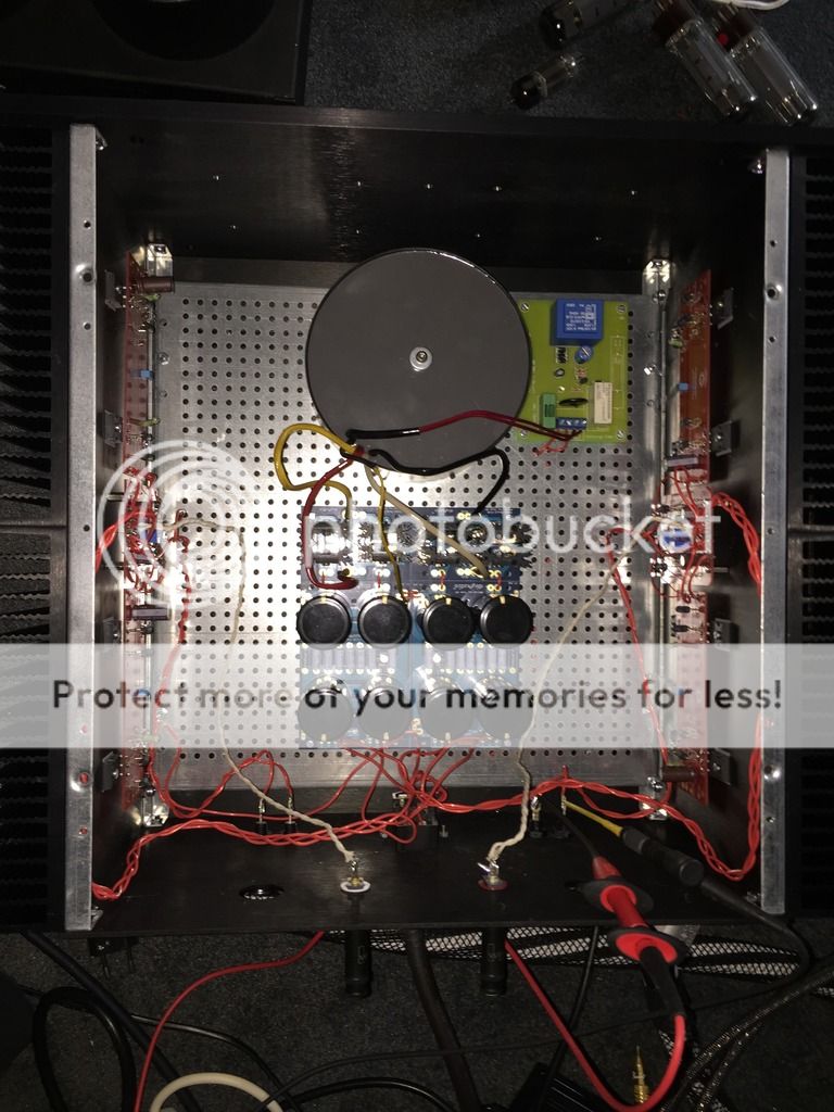
do you mind posting some pictures of amp ?
that big difference of output offset open inputs vs. closed ones isn't good
that big difference of output offset open inputs vs. closed ones isn't good
I will, but may I ask how yours is behaving, so what is normal ? I may up ending including the cascode I guess, which I do not have currently...maybe the voltage is a bit to high for an input setup without cascode ?
The boards and the fets are from the diyaudio-store.
The boards and the fets are from the diyaudio-store.
Last edited:
I had F5 on my bench eons ago , but if memory serves me , it didn't show that much difference

I am not at home currently, need to x-check. Usually I connect the protection earth from the power plug directly to the chassis and the ground of the psu in parallel. So, i for sure did not use a diode bridge with parallel th as I used a separate start-up relay with psu filter already...or must the diode bridge be used to separate ground and earth here ?
Hi Blitz.
If i remind right any builders use there a CL30/CL60.
ZM and 6L6 could help you very much better.
cheers.
If i remind right any builders use there a CL30/CL60.
ZM and 6L6 could help you very much better.
cheers.
I am not at home currently, need to x-check. Usually I connect the protection earth from the power plug directly to the chassis and the ground of the psu in parallel. So, i for sure did not use a diode bridge with parallel th as I used a separate start-up relay with psu filter already...or must the diode bridge be used to separate ground and earth here ?
Hi Blitz.
If i remind right any builders use there a CL30/CL60.
ZM and 6L6 could help you very much better.
cheers.
Check the psu schematics from the F5turbo article and you'll find an diode bridge with CL30/60.
No.Yes MaSantos, that it is- isolating to ground the Amp to PE.
Cheers.
That is the safety connection for the exposed conductive parts.
Blitz - To clarify, there should be a simple wire connection from the AC plug earth to chassis.
The connection I'm asking about is from PSU ground to chassis - this should have a diode bridge and/or CL-30, -50, -60 from GND to chassis, to introduce a few ohm between that GND and the chassis. (and to have enough current capability in case of a fault where that connection must flow current to chassis to earth)
The start-up relay doesn't change how you need to wire this - Chassis directly to AC mains earth, PSU ground needs Thermistor or similar between it and chassis.
Andrew - Please read everybody's posts again before commenting with sharply negative and generally unhelpful information. Blitz already said he had a wire from AC safety earth to chassis, and both commenters were taking about the PSU to chassis connection.
I did read that post.Blitz - To clarify, there should be a simple wire connection from the AC plug earth to chassis.
The connection I'm asking about is from PSU ground to chassis - this should have a diode bridge and/or CL-30, -50, -60 from GND to chassis, to introduce a few ohm between that GND and the chassis. (and to have enough current capability in case of a fault where that connection must flow current to chassis to earth)
The start-up relay doesn't change how you need to wire this - Chassis directly to AC mains earth, PSU ground needs Thermistor or similar between it and chassis.
Andrew - Please read everybody's posts again before commenting with sharply negative and generally unhelpful information. Blitz already said he had a wire from AC safety earth to chassis, and both commenters were taking about the PSU to chassis connection.
I stand by the correction I made.
The PSU to Chassis connection is ONLY a safety connection. It has nothing to do with audio performance.
The PE to Chassis connection is another safety connection. Again it has nothing to do with audio performance.
Guys, thx a lot for your time and energy trying to help.
My setup is precisely sofar:
- Earth from the power plug goes with one cable directly to PSU ground
- Into the same pad a cable goes from there to chassis
- from the psu ground, the pcbs got connected
I am just in the process of including the bridge between psu ground and earth. Will take a few days.
Just to be sure on setting the bias: Do you use a load resistor on the speaker output or is the output un connected ?
Best Regards
- Home
- Amplifiers
- Pass Labs
- F5 Turbo Builders Thread