Ok I will try to measure across the 10 ohm if it is possible thanks
Buzz is referring to resistors R3 and R4 which are 10R each. Measure voltage across each with P1 and P2 turned off and divide this V by 10r and you will get the current flowing in the Jfet.
nash
Buzz is referring to resistors R3 and R4 which are 10R each. Measure voltage across each with P1 and P2 turned off and divide this V by 10r and you will get the current flowing in the Jfet.
nash
Thanks Then I must take the time removing all the big capacitors to make some arrangements to make it possible to measure.
0r2 for the minimum is good. That is where you set the pot for first start up.0,2 ohm and 1260 ohm A little bias at positive side and nothing at negative. I ordered 3,9 kohm resistors as R 5 and R 6. Must wait to they arrive
1260r for maximum means that 4mAof Id will develop 5V to be applied across GS and Re.
%mA gives an even higher 6.3V to be applied across GS+Re
That is plenty to bias up the output stage.
5mA of Id would be ~ 62% of 8mA Idss
Is the other half similar resistance?
Last edited:
0r2 for the minimum is good. That is where you set the pot for first start up.
1260r for maximum means that 4mAof Id will develop 5V to be applied across GS and Re.
%mA gives an even higher 6.3V to be applied across GS+Re
That is plenty to bias up the output stage.
5mA of Id would be ~ 62% of 8mA Idss
Is the other half similar resistance?
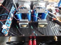
Yes similar but no bias whatsoever. Biggest problem is the way Pcb is mounted combined with PCB design. It is impossible for me to reach the points to measure the voltage over r 3 and r4. And again I only have +/- 32 Vdc in supply. Looks like a mess and enclosure is stupid to. Have to take everything out to reach the screws at the bottom into the heatsink. Think I will forget about this amp for some weeks.
Attachments
Last edited:
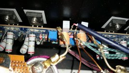
That pic of all those cable joints tells me there is something wrong with the layout of the wiring.
EVERY circuit has a two wire connection,. The Flow of current from the Source and the Return of that current to the Source. Wire EVERY circuit as a two wire pair !!!!!!!!!!
EVERY circuit has a two wire connection,. The Flow of current from the Source and the Return of that current to the Source. Wire EVERY circuit as a two wire pair !!!!!!!!!!
If you want to measure the voltage across R3 and R4, it will be the same as the voltage between ground and either 1) the source pin of the JFET, which should be accessible even through that mess and 2) the lower end of the large feedback resistors, which should be somewhere towards the middle of the board.
You will also be able to make a good guess about the JFEt operation by measuring the voltage across the trimmer while the amp is running, if you're sufficiently careful. First you have to set the trimmer to a known resistance (say, 200 ohm) while the amp is off and measure the vltage across it while the amp is running. You will get the current flowing through the front end.
When building these amps I always test them with a low current fused power supply, with no output devices installed. I ensure there is at least 6V of bias voltage available by measuring the G-S pins of each device at max bias position (max resistance), then reset the pots to zero, attach the output devices and heatsinks etc. Just saves a lot of trouble later.
I would also double check the PCB against the circuit. Strange things can happen when using 'original' PCBs. Reversed and misprinted silkscreens are very common - mostly because all of these are produced using a layout editor with parts in the stock library, which are not always correct. Do check that all device terminals are correctly located and have the appropriate voltages.
Sa 1837 orientation
MOSFET High Power 100W Pure Class A Amplifier Thick PCB Turbo V3 Stereo | eBay
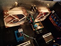
Looks like I mounted the SA 1837 the wrong way. I screwed it and the 2 SC 4397 both with back to heatsink. Logical for me but it must be faulty. The drivers need heatsinks I presume?
MOSFET High Power 100W Pure Class A Amplifier Thick PCB Turbo V3 Stereo | eBay
Looks like I mounted the SA 1837 the wrong way. I screwed it and the 2 SC 4397 both with back to heatsink. Logical for me but it must be faulty. The drivers need heatsinks I presume?
Last edited:
That picture does not have sufficient resolution, but it looks like the silkscreen for the J74 is backward, the leftmost terminal is the drain and should connect to the emitter of the 1837. As I already suspected, this is typical error and should be checked against schematic and part datasheets. I am not sure of any other mistakes, but I'm not going to bet against it.
The 1837 and 4793 are not drivers, they are cascodes and should survive without a heatsink. A small one is advisable, but that design does not look like it has any space at all for such a thing.
The 1837 and 4793 are not drivers, they are cascodes and should survive without a heatsink. A small one is advisable, but that design does not look like it has any space at all for such a thing.
Last edited:
That picture does not have sufficient resolution, but it looks like the silkscreen for the J74 is backward, the leftmost terminal is the drain and should connect to the emitter of the 1837. As I already suspected, this is typical error and should be checked against schematic and part datasheets. I am not sure of any other mistakes, but I'm not going to bet against it.
The 1837 and 4793 are not drivers, they are cascodes and should survive without a heatsink. A small one is advisable, but that design does not look like it has any space at all for such a thing.
CLIC ON THE PICTURE AND IT WILL ZOOM. I am sure the SA 1837 is mounted the wrong way around.
The opened picture is what I was talking about (size is fine, the resolution is low making deciphering of individual tracks difficult) but do note the J74 silkscreen is reversed - along with any other mistakes you might find. You will have to fix that. It is possible that cheaper Chinese '2SJ74' is a faked SJ103, which has reversed D-S pins.
The 1837 is marked correctly on the PCB in spite of how you have mounted it. The emitter of TO-220 devices is the right most terminal. This means the side you would normally mount on the sink is facing into the board.
Frankly, the layout makes no sense at all and you would have been better served by using a quality PCB instead. Note that sometimes sellers will have an old picture on the listing and the PCB sent to you may have been revised. There is no substitute for checking the connections and device pins against a datsheet and measurement, rather than taking the seller's word for it or assuming their drawings are correct.
Specially when they have official presence here and no way to answer your questions. I have dealt with this seller and I find his customer support beyond reproach, but not sure of the PCB design ability.
Anyway, have fun troubleshooting") That's as much part of the journey of learning and discovery as the enjoyment of a finished product.
That's as much part of the journey of learning and discovery as the enjoyment of a finished product.
The 1837 is marked correctly on the PCB in spite of how you have mounted it. The emitter of TO-220 devices is the right most terminal. This means the side you would normally mount on the sink is facing into the board.
Frankly, the layout makes no sense at all and you would have been better served by using a quality PCB instead. Note that sometimes sellers will have an old picture on the listing and the PCB sent to you may have been revised. There is no substitute for checking the connections and device pins against a datsheet and measurement, rather than taking the seller's word for it or assuming their drawings are correct.
Specially when they have official presence here and no way to answer your questions. I have dealt with this seller and I find his customer support beyond reproach, but not sure of the PCB design ability.
Anyway, have fun troubleshooting
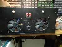
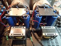
That's as much part of the journey of learning and discovery as the enjoyment of a finished product.The PCB you use, Drossel, is taken from Jims Audio. There is a lot of builders that have bought Jims PCB for variation F5 builds. I have also built F5V3 Turbo with the same PCB as you do now, but with no problems. The PCB is ok with no faults as far as I can see. I do not use MUR diodes at all. Power is +/-42.5 V DC and bias is 2.4 A. PC blowers helps keeping the teperature inside the cabinet low. It does not influence much on the heatsinks temp. I bring you some photos.
Eivind S
Eivind S
Attachments
Fake 2Sj74 and 2SK170BL from china is a problem. Short time ago I return 40 psc. 2SK170BL that claimed to be genuine. They all measured a Idss as high as 17-18mA. They could have been a 2SK170 K grade. From France I bought real genuine 2K170BL, orginaly used for building microphone preamplifiers, and to a fair price too. He also have 2SJ74BL.
Isnt the SA 1837 orientation marked on the PCB? May be I have a photo. I will look.
Eivind S
Isnt the SA 1837 orientation marked on the PCB? May be I have a photo. I will look.
Eivind S
Fake 2Sj74 and 2SK170BL from china is a problem. Short time ago I return 40 psc. 2SK170BL that claimed to be genuine. They all measured a Idss as high as 17-18mA. They could have been a 2SK170 K grade. From France I bought real genuine 2K170BL, orginaly used for building microphone preamplifiers, and to a fair price too. He also have 2SJ74BL.
Isnt the SA 1837 orientation marked on the PCB? May be I have a photo. I will look.
Eivind S
Yes it is marked but I thought logical was on the heatsink. I have bought a lot 2 Sk 170Bl from France to
Drivers should not be mounted on the common heatsink.
Eivind S
And it is not drivers but cascode transistors. I make to many amplfiers. So concentration is not 100 %
The PCB you use, Drossel, is taken from Jims Audio. There is a lot of builders that have bought Jims PCB for variation F5 builds. I have also built F5V3 Turbo with the same PCB as you do now, but with no problems. The PCB is ok with no faults as far as I can see. I do not use MUR diodes at all. Power is +/-42.5 V DC and bias is 2.4 A. PC blowers helps keeping the teperature inside the cabinet low. It does not influence much on the heatsinks temp. I bring you some photos.
Eivind S
The J74 is reversed.
Check the datasheet. Look at the PCB.
The K170 and J74 have identical pinouts.
The PCB mirrors them. This means the Drain has moved to the oposite side of the board, the tracks must cross over the device.
It does not do that - so the PCB is faulty.
Is it possible to have a working board with a reversed JFET? Yes, because JFETs will often operate with reversed D-S.
That still doesn't make it correct. It's mortifying that such mistakes should be even justified.
Are you sure the PCB is faulty? I think Jim did that on purpose so he could use the cheaper 2SJ103. The 103 fit the layout perfect or am I wrong?The J74 is reversed.
Check the datasheet. Look at the PCB.
The K170 and J74 have identical pinouts.
The PCB mirrors them. This means the Drain has moved to the oposite side of the board, the tracks must cross over the device.
It does not do that - so the PCB is faulty.
Is it possible to have a working board with a reversed JFET? Yes, because JFETs will often operate with reversed D-S.
That still doesn't make it correct. It's mortifying that such mistakes should be even justified.
I checked datasheets and with no doubt you are right. Jim had no 2SJ74 so he used the 2SJ103. If I have not done that fault with Sa 1837 I would not discover it. I sent a message about this to Jim and he did not answer. UPS are bringing me the new Jfets soon. I also ordered new pots so it will be easier to adjust.
Komponenter >> Potentiometer >> Trimmere >> Multiturn >> 3296P - 20-25
Last edited:
- Home
- Amplifiers
- Pass Labs
- F5 Turbo Builders Thread