The heat sinks are not depicted in the photos, but here now. The alloy plate= 222mmx400mmx10.9mm, the fins are 222mmx95mmx70mm, each assy =9kgs, I milled a couple of thou off the mating face of the fin's, to get a better contact.
Seems not enough for an F5T.
Typo that I did not check and eliminateYes and by my experiments with 240Vac you should find that by restricting the worst case starting current to ~16A that the T8A fuse will not blow. 115Vac/16Aac = 7.2Aac.
A resistor of 6ohms to 8ohms should limit the current correctly.
it should have said
Yes and by my experiments with 240Vac you should find that by restricting the worst case starting current to ~16A that the T8A fuse will not blow. 115Vac/16Aac = 7.2ohms.
A resistor of 6ohms to 8ohms should limit the current correctly.
Seems not enough for an F5T.
Agreed.
Contact patches in that layout are extremely small. I have some heat islands with just 2.5" gaps on a specific sink with a raised contact patch, it seems your gaps are much larger. Heat does not travel well laterally. I solved the issue using a set of heatpipes, which work extremely well. I still have some temperature differences, but half of what they used to be.
At the expense of fin orientation, I would urge you to consider mounting the sinks such that the transistors mount directly over the contact patch. But you would need more sinks in that case, maybe two more to take the total to 8 (4 per side, one on top and one on the bottom.
Another way to look at it, though I am not sure about the wiring, if you rotated the output PCBs 90 degrees you could get each device on top of a sink contact patch. I have no idea how that PCB set would fit together in that event though.
advice required
Hi
Many Thanks for your suggestions
Have ordered 4 more heat sinks of same size/spec, now making 5 verticals per side, this allows each transistor to mount directly over a contact patch of a heat sink.
Any thoughts on my original inquiry
Regards
Agreed.
Contact patches in that layout are extremely small. I have some heat islands with just 2.5" gaps on a specific sink with a raised contact patch, it seems your gaps are much larger. Heat does not travel well laterally. I solved the issue using a set of heatpipes, which work extremely well. I still have some temperature differences, but half of what they used to be.
At the expense of fin orientation, I would urge you to consider mounting the sinks such that the transistors mount directly over the contact patch. But you would need more sinks in that case, maybe two more to take the total to 8 (4 per side, one on top and one on the bottom.
Another way to look at it, though I am not sure about the wiring, if you rotated the output PCBs 90 degrees you could get each device on top of a sink contact patch. I have no idea how that PCB set would fit together in that event though.
Hi
Many Thanks for your suggestions
Have ordered 4 more heat sinks of same size/spec, now making 5 verticals per side, this allows each transistor to mount directly over a contact patch of a heat sink.
Any thoughts on my original inquiry
Regards
The distance to the outputs from transformers is okay. I work with less than that most times because of the exact same reason, though I prefer to have wider cases. The 17" standard does not worry me personally, though some builds become very tight when trying to stick to it.
Inductors, not so sure. Normally we do rotate them to ensure reduced coupling, specially with air-core units with such small spacing. You can expect some coupling between them because you have them oriented similarly and very close, not a good combination.
Inductors, not so sure. Normally we do rotate them to ensure reduced coupling, specially with air-core units with such small spacing. You can expect some coupling between them because you have them oriented similarly and very close, not a good combination.
Hello. Please help me answering the dumb question below....
I'm using the diystore universal PSU board for my build, and I got the dual cathode rectifiers (TO-3P case) FEP30DP for that board that are shown in the image below.
Question: Do I need to cut one of the 2 anode legs on each of these dual rectifiers in order to have only 4 diodes per bridge (instead of 8)? If not, then why are both anode legs needed at the same time?
Thanks!
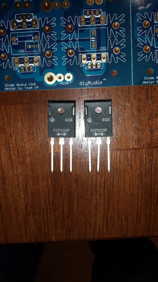
EDIT: Never mind. Question already answered. Thanks.
I'm using the diystore universal PSU board for my build, and I got the dual cathode rectifiers (TO-3P case) FEP30DP for that board that are shown in the image below.
Question: Do I need to cut one of the 2 anode legs on each of these dual rectifiers in order to have only 4 diodes per bridge (instead of 8)? If not, then why are both anode legs needed at the same time?
Thanks!
EDIT: Never mind. Question already answered. Thanks.
Last edited:
Ok guys, I already (or almost?) finished my F5 Turbo V2 build. I adhered to the schematic in the article except that I used pairs of 0.68ohms source resistors to get 0.34ohms source resistance instead of 0.5ohms as in the schematic (since I want to be able to bias above 40w class A at 8ohms), and I also used cascode as my rail voltages are around +-36V.
It seems to be working well after the initial setup, BUT the major problem I have is that when increasing the bias from zero I cannot get above 124mV across the source resistors! (if output DC voltage is 0mV as desired), the trimpot P1(5kohms) run out of turns at that voltage at source resistors. I'm getting 124mv in P channel, 120mV in N channel and +-3.0mV DC ouput. And I wanted to go to around 350-360mV ! so it looks I'm quite far from being at that value . I get the same results basically in both left and right channels.
I know I could increase the 1Kohm resistance that is in parallel to the source resistors, BUT is it not too strange that I'm getting bias this low in the first place? or can it be normal in some cases? I got my matched jfets and Turbo kit Mosfet from diyaudio store, as well as the pcb's, so I would think all these should not be the problem.
Any ideas if something sounds totally wrong?
Thanks in advance
It seems to be working well after the initial setup, BUT the major problem I have is that when increasing the bias from zero I cannot get above 124mV across the source resistors! (if output DC voltage is 0mV as desired), the trimpot P1(5kohms) run out of turns at that voltage at source resistors. I'm getting 124mv in P channel, 120mV in N channel and +-3.0mV DC ouput. And I wanted to go to around 350-360mV ! so it looks I'm quite far from being at that value
. I get the same results basically in both left and right channels.I know I could increase the 1Kohm resistance that is in parallel to the source resistors, BUT is it not too strange that I'm getting bias this low in the first place? or can it be normal in some cases? I got my matched jfets and Turbo kit Mosfet from diyaudio store, as well as the pcb's, so I would think all these should not be the problem.
Any ideas if something sounds totally wrong?
Thanks in advance
Last edited:
Cost of F5T build
I was trying to estimate how much an F5T would cost to build. I was uncertain as to which MOSFETS were available and which were the easiest to source in the UK?
Similarly (I haven't read all 400+ pages so forgive me) but which size of transformer would one need for 50 watts class A - ? 1kva and what is the best reliable source for these?
Thankyou.
Jd,
did you measure your jFETs?
Andrew, no I did not, my bad. I assumed they were good enough to solder right away since they came from diyaudio store as 2 matched pairs (49.99 dollars the quartet), so I did not want to get into measurements since I'm not too well versed on this.
Are you suspecting my jfets could be causing this very low max Bias in my setup? If so, what do you suggest to measure? Idss?
I originally said that I had the same results on left and right channels but that was not quite right, I might have messed up measurements while tired/sleepy. These are the actual max voltages I'm getting across the Source resistors:
Left channel:
Drop across Rs at P-channel = 124mV
Drop across Rs at N-channel = 120mV
Output = +- 5 mVdc
Right channel :
Drop across Rs at P-channel = 101mV
Drop across Rs at N-channel = 110mV
Output = +- 4mV
As Jim said, this maybe common and normal, but strange for me anyway at this low max voltage (only 101mV max across source resistance at one of the p-channels?). I'll try compensating with more parallel resistance at the trim pots as Jim suggests.
Last edited:
Here is another bias problem, not very commond to jedecs, but "new" for me. I have built many F5, all vertions. This is a F5 V2. When I measured the bias I got this results: On the N side: 250 and 250 mV. On the P side 340 and 160 mV. No problem to set a very low offset. Sourceresistors as well as N-FET and P-FET are very close matched, So why do I get so different results on the P side? Could it be a mismatch other places like between 2SK170 BL and the 2SJ74. Does anyone have simple "cure" to this problems. I have never run into this in my earlier F5 builds.
Eivind S
Eivind S
According to the N reading, you are biasing at around 0.56A per fet.
Try matching a pair of P-fet at the same bias point to see it will help, ideally both at around 50C.
You may have 2 P-fet's that differentiate quickly as the temp rise. Or, you may have one fet hugging the heatsink better than the other??
Try matching a pair of P-fet at the same bias point to see it will help, ideally both at around 50C.
You may have 2 P-fet's that differentiate quickly as the temp rise. Or, you may have one fet hugging the heatsink better than the other??
The low bias startet already from the first time I fired up using my variotransformer, so for me it is "difficult" to see that the two P-FETs behave differently on the temerature on the heatsinks. So far I find this results on this amplifiers biasing difficult to "understand".
Eivind S
Eivind S
Problem solved. With two new P FETS, bias on both sides are very close. But what the the reason for this failure was is still a "mystery".
Eivind
More than likely the Vgs of the two Fets are not the same. I know you said that they were matched but measure them now and let us know. I had a similar frustrating problem building my F5TV3 four pairs. Sometimes position also makes a difference but not too much. Interface matters too but since you have the difference in the two P fets from startup likely it is different Vgs.
nash
- Home
- Amplifiers
- Pass Labs
- F5 Turbo Builders Thread