more info about soft start boards
Sorry forgot to add this
Ebay Item # 121239778994
ZM I remember in the past you had suggested replacing the four NTC's found on these with two CL60's in series but not sure whether this solves my problem
Thanks.
sounds like the NTC's do not get bypassed after startup. then they will still be hot and low impedance after a minute or 2.
and yes. this NTC's are connected 2 and 2 in paralell, wich is a very bad idea.
When I press the momentary start switch I first hear the transformer hum and then after two seconds or so I hear the relays of the soft start click. So I assume that this is when they are bypassed. Right?
When I press the momentary start switch I first hear the transformer hum and then after two seconds or so I hear the relays of the soft start click. So I assume that this is when they are bypassed. Right?
When you turn off the amp do you hear any clicks to indicate that the relay has reset itself?
When you turn off the amp do you hear any clicks to indicate that the relay has reset itself?
Yes you hear the relay click when either the momentary switch is pressed or the power switch is switched off.
Draw the soft start schematic and post that here.
Show how you wired the mains through the soft start to your transformer.
Sorry Andrew it being an Ebay soft start there are no schematics.
There are four spades on the softstart. Two are for the hot and the neutral which come from a double pole power switch. The other two spades are connected to the transformer primary windings.
Nash
OK. I did a bit more experimenting around today.
Using only the momentary switch to shut off and turn on the amp results in no problem. I tried it several times putting it off and on even within 5 seconds and no problem. If however you turn off the power switch and then immediately press the momentary switch chances are the fuse blows. I suspect this may have something to do with a cap/s on the softstart charging/ discharging.
So just to share my experience with others who are using the Ebay type softstart if you wish to shut off the amp for a short while just use the momentary switch to do so, dont use the power switch.
Nash
I trace out the circuit of one of the Ebay softstart boards comparing with the boards I previously used. The circuit was way too complex for what it was supposed to do so I cut some traces and jumpered it to work my way.
You must first understand how the circuit works then you can figure out how it is not working as to how it should work, or how you want it to work.
If you can supply a schematic we could help.
Good luck.
You must first understand how the circuit works then you can figure out how it is not working as to how it should work, or how you want it to work.
If you can supply a schematic we could help.
Good luck.
Folks:
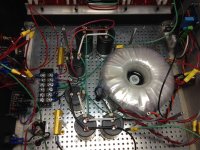
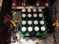
As much as I have enjoyed my F5T V3 monoblocks over the past 15 months or so, I was a little disappointed that they lacked some of the authority and weight that the Aleph 1.2 monoblocks they replaced had in spades. I had hoped that fiddling with P3 would work, but that effort proved ill-fated (see http://www.diyaudio.com/forums/pass-labs/267431-f5-turbo-3-failure.html). Instead of gambling against the odds a second time, I spent part of this past weekend adding another 90,000 uF (and a 0.5R / 50 watt resistor) to the stock-sized power supply in each amp, bringing the total to 250,000 uF per monoblock. The power supply capacitors (twenty-two per amp) are all Nichicon KG. This won't come as a surprise to most of you, but the results are terrific -- there is no bloat, the amps still sound neutral, fast and dynamic and my V3s are more commanding and engaging than before. Highly recommended!
Peace and love, peace and love.
Regards,
Scott
Attachments
This won't come as a surprise to most of you, but the results are terrific
Cool!
Folks:
Instead of gambling against the odds a second time, I spent part of this past weekend adding another 90,000 uF (and a 0.5R / 50 watt resistor) to the stock-sized power supply in each amp, bringing the total to 250,000 uF per monoblock.
This won't come as a surprise to most of you, but the results are terrific -- there is no bloat, the amps still sound neutral, fast and dynamic and my V3s are more commanding and engaging than before. Highly recommended!
Yep, more caps always help. a bigger transformer helps too

When I built the F5TV3 I went all the way with 564000uF and 1.5kVA trafo per mono. I don't think I've ever been able to clip it or have music compress yet with several systems its been on

I finished my build of a V2 last week and everything is working great except for setting my bias. The max I can get, with a DC offset of 0V, is around .170V. At that bias you can hardly tell the amp is on when you touch the heatsinks. I know I should be getting a lot more out of it. After searching the forum it looks like I need to increase the value of R5 and R6. What value should I increase these to and what would cause the bias to max out so low?
Thanks for any input.
Thanks for any input.
It's a combination of lower than average Idss of the Jfet and higher than average Vgs of the Mosfets.
No big deal, makes zero difference in sound quality. Just increase R5, R6 until you can get 0.35V across the source resistors. Start with 2.2K or thereabouts and increase if necessary.
No big deal, makes zero difference in sound quality. Just increase R5, R6 until you can get 0.35V across the source resistors. Start with 2.2K or thereabouts and increase if necessary.
- Home
- Amplifiers
- Pass Labs
- F5 Turbo Builders Thread