Yes, they were spot/point matched, BUT more importantly they were matched over a range of currents by selecting gm as a second matching criteria.Nic's mosfets were matched for Patrick's (EUVL) F5X at 16VDC, 2A, and 60C...................
They were matched for BOTH Id and gm as Vgs was swept through the expected working range.
This is matching in the proper sense implied by the word "matched".
Euvl's "team" volunteered to do a lot of work and develop a lot of jigs/methods to ensure the success of the F5x project.
Thanks to them all.
Folks:
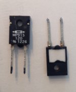
Just a quick head's up for those few of you who, like me, are relative newbies. I used 120 ohm Caddock MP915 resistors in lieu of the 220R resistor pairs at R7/R8 and R9/R10 on the F5T front end board (store boards, version 3.0). I mistakenly understood the MP915 resistors were rated for 15 watts with small heatsinks. The BOM calls for 3 watt resistors at R7-R10, making two pairs of resistors having the effective value of 110R / 6 watts. My MP915 resistors and their tiny heatsinks were not up to the task; the photo shows their deformation (see the dimple between the resistor legs). Their readings are now far from 120R.
I'm migrating to 220R 3 watt Vishay/Dale resistors (RS02B220R0FE70 Vishay / Dale | Mouser).
Regards,
Scott
Attachments
Buzz:
There are two answers, because there were two instances. As you may recall, I built two F5T V2 amps and one set of V3 monoblocks. One of the V2 amps spontaneously blew and I believe the MP915 resistors were involved. I've only just begun diagnosing that amp's problems. The second instance was with one of my V3 monoblocks; that amp blew when the power and ground connections to the front end board were broken while adjusting P3. During the process of fixing that amp, I took a closer look at the other, functioning V3 monoblock and discovered that the MP915 resistors were no longer operating at 120R (one was about 230R and the other a little higher). I'm now going to replace all of the MP915 resistors in the V2 and V3 amps as a precaution.
Regards,
Scott
lhquam:
Sorry, but I don't have the part numbers. They are small clip-on heatsinks scaled for the MP915 and were supplied as part of a group buy.
The point is if you are using the MP915 resistors, you may want to consider attaching a substantial heatsink or replacing them with something else.
Regards,
Scott
During the process of fixing that amp, I took a closer look at the other, functioning V3 monoblock
So maybe the mono-block that was damaged by the disconnected ground, that sounded like it had lower output, is in fact OK after repair? Just trying to understand where we are. You would be right to replace all the power resistors.
We can take a look at testing the mosfets and all semis on the V2 amp, when you have time.
Process of elimination in action. Good work.
Vince
It is very possible the in the higher power versions, the resistors should be scaled up in their power ratings. I have done one 4 output pair version, but not running at full bias and on slightly lesser rails of about 27 V. In that instance, I had no issue at all and the amp ran for about six months.
Vince:
Thanks! I'll be in touch once the resistors are in.
Buzz:
Three of the four amps (one V2 and the two V3 monoblocks) have 32V secondaries; the rails are running around 44.5VDC. I thought I set the bias on those amps conservatively, but they may be running hotter than expected. Curiously, the fourth amp (a V2), with 24V secondaries, has shown no problems. Still, I'll be swapping the MP915 resistors out of that one as well.
Regards,
Scott
Folks:
Just a quick head's up for those few of you who, like me, are relative newbies. I used 120 ohm Caddock MP915 resistors in lieu of the 220R resistor pairs at R7/R8 and R9/R10 on the F5T front end board (store boards, version 3.0). I mistakenly understood the MP915 resistors were rated for 15 watts with small heatsinks. The BOM calls for 3 watt resistors at R7-R10, making two pairs of resistors having the effective value of 110R / 6 watts. My MP915 resistors and their tiny heatsinks were not up to the task; the photo shows their deformation (see the dimple between the resistor legs). Their readings are now far from 120R.
I'm migrating to 220R 3 watt Vishay/Dale resistors (RS02B220R0FE70 Vishay / Dale | Mouser).
Regards,
Scott
I remember reading that the free air dissipation of the 915series is 1.75W. Did you use a thermal grease between it and the heatsink?
The Vishay Dale wirewounds are also available in a non inductive style. NS instead of RS in the numbering. The leads are however magnetic (for the CW, NS and RS ) being made from Copperweld if that bothers you.
Also if you need a bit more gain in your setup now would be the opportune time to change these values.
Nash
free air dissipation of the 915series is 1.75W
915 series dissipation is 1.5w without a heat sink. I think it lasted as long as it did because it had a heat sink, even without grease. The heat sink is a clip on, not screw-down type.
What I don't understand is the result. The resistor(s) didn't burn-out or break completely. I get that. What I find funny is the resistance increased. Can anyone explain that? Did the excessive heat increase the element size?

Maybe here's some answers.
MECHANICAL FAILURES
Apart from the obvious precautions required to prevent handling damage leading to cracks and chips to the resistor material most mechanical damage is caused by stresses induced by vibration or inappropriate mounting of the device.
http://www.tsec.ltd.uk/main-causes-thick-film-resistor-failure
Ongoing vibration can cause micro cracking of the resistor material that will lead to change in the resistance value, damage to the resistive element or (often if combined with other stresses such as thermal) component failure.
Last edited:
Also if you need a bit more gain in your setup now would be the opportune time to change these values.
Nash
I agree, I've used just one 200R MP915 (so 2 in total) with those tiny heatsinks, to give roughly a 6 db gain and I've had no problems after 8 months of pretty much continously being on.
And this is on a V3 with 50V rails.
for 230Vac - CL60 or , even better , CL70
Ok, thanks!
Okay, I'm starting to melt some solder! But I need a little hand holding. My build is F5T V2 cascode, dual mono with Antek AS4224 transformers (400VA, 24V.) This will yield rail voltages of +/- 32V. I have calculated R27,R28 at 6.34K which will give me 12.4V (approx) VDS across the JFETS. My concerns are:
1. Did I calculate this correctly?
2. Is 12.4V a good VDS for these devices? Or is there any value to running higher VDS?
As this is my first build in about 30 years, I am opting to start out conservatively. Once I have a little more confidence in what I'm doing I can start the journey to full-fledged FAB.
Thanks, Hal
Soft start problem
I am using the red Ebay soft start protection board (120V) for my F5Tv3 for about a month now.
When I start the amps from cold I flip the power switch at the rear of the amp, press the momentary button and the amp starts without a problem. When turning off I flip the switch only.
The problem is that when I turn off the amp and restart within a couple of minutes the amp fuse blows. Fuse is the recommended 4A slo blo. Why is this happening? Am I supposed to turn off by pressing the momentary switch first? Both mono amps with similar soft starts do the same thing.
Advice would be appreciated. Thanks.
Nash
- Home
- Amplifiers
- Pass Labs
- F5 Turbo Builders Thread