Hi
Had my regular F5 now for a year. Sound is great, however this evening I turned it on and heard a crackling sound. Took the lid of and saw a small spark coming from the + terminal of one of my Fairchild bridge rectifiers. I guess the part is fried on the inside and needs replacing?
My heatsinks are only 4" tall by 14 long, which mean the amp is hot to touch 50deg C and pretty warm inside. The rectifiers are screwed on to the bottom aluminium plate of the amp chassis.
FQA12P20 and FQA19N20
Hi All,
I am not sure if people know of this company that do end of life parts but I found that they stock the FQA12P20 and the FQA19N20. here is the link:
Active and Obsolete Parts and Semiconductors - Rochester Electronics
According to the site they have 1000+ of each. I'm getting a quote as we speak for 25 of each.
Last edited:
I use the TO-220 FQP because they are still in production.
Me being paranoid and anxious of fakes.
Me being paranoid and anxious of fakes.
Hi All,
I am not sure if people know of this company that do end of life parts but I found that they stock the FQA12P20 and the FQA19N20. here is the link:
Active and Obsolete Parts and Semiconductors - Rochester Electronics
According to the site they have 1000+ of each. I'm getting a quote as we speak for 25 of each.
Mind that they offer only the FQA19N20 L
The L type has a much lower Vgs threshold and a very high transconductance value than the type without suffix or the C type.
Matching them with the P type could give a very high 2nd harmonic distortion.
")
Folks:
I'd appreciate your advice regarding fuses on an F5T V2. The amp includes the following:
120 VAC mains
diyAudio soft start board v2, with four 75R power resistors and a 1uF X-class cap in the C9 position
1000 VA SumR toroid with 24 VAC secondaries
Dual bridges, sixteen 10,000 uF Nichicon KG caps in the power supply
diyAudio F5T boards, MOSFETs biased to .9 A
diyAudio speaker protection board v2
DC offset of under 2.0 mv
I've been using 4 Amp slo-blo fuses and every once in a while they blow. Should I be using 5 Amp slo-blo fuses or is there a problem that needs addressing?
Regards,
Scott
Last edited:
without a soft start the 1000VA 115Vac transformer could be expected to need a 20A to 25A fuse to allow it to start up.
Using the correctly implemented soft start allows a close rated fuse to be used.
If the transformer is severely over-rated for the duty, then you can reduce the fuse slightly, but 50% is going far too far. Even going to T5A is de-rating the fuse by ~40%
T6.3A may work reliably in the long term if the transformer is never used to full rating.
DiyA softstart is having 4pcs 75R resistors in parallel , which I recently told that's no-no
replace them with 2 or 3pcs of CL60 in series and you'll have really soft start
problem is that , with soft start circuits with fixed resitors , RC constant is critical - something is gonna fail eventually - either fuse or relay contacts
replace them with 2 or 3pcs of CL60 in series and you'll have really soft start
problem is that , with soft start circuits with fixed resitors , RC constant is critical - something is gonna fail eventually - either fuse or relay contacts
I blew a JFet on one of my channels because I put them in the wrong place. The JFETs where from Buzz's GB. I got a full new set from FET Audio in Singapore. Should I A) replace them all on both channels so they are from the same source/batch or B) just replace the bad channel? I figure I should replace them all to be sure the IDSS matches? Of course I have no idea what I am talking about...
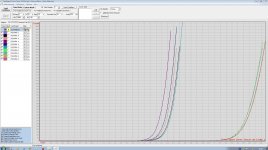
Im finally up to assembling the F5TV3.
I'm testing each and every stage before I go on.
I just powered the FE board.
I'm getting 58V from TP1 to PS ground as well as TP3 (note my PSU is 58V unloaded)
I haven't turned up P1 and P2 yet and its running about 1.6V across TP1 /TP2 and TP3 /TP4 respectively.
However, I;m only getting 50mV from source to ground at both the Jfets
and 0.8V from Drain to ground on Q1 and 0.6V from drain to ground on Q2.
Is this correct? I was expecting about 15V.
Note R25 and R26 has been changed to 12K and R28 and R27 is still 4.75K.
Did I do something wrong? or do I have to connect the output boards before the jfets see higher V?
Attachments
1837 should be on pos rail, so you should be fine. Dont have the boards, so it is hard to follow. Crummy thing is, if something is wrong with the bjt's, it probably cooked the Jfets as well. Measure the voltage across the 4.75k resistors to see what V drop you are getting.
1837 should be on pos rail, so you should be fine. Dont have the boards, so it is hard to follow. Crummy thing is, if something is wrong with the bjt's, it probably cooked the Jfets as well. Measure the voltage across the 4.75k resistors to see what V drop you are getting.
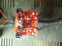
Oh crap. I don't think 1837 is on +ve rail.
The +ve rail is the bottom side in my pic. it has the 4793 in it. as well as the k170 (Q1 as marked on the board)
the -ve rail is on the top and that has the 1837 and J74(Q2 as marked on the board)
Is there a build guide somewhere using the V2.0 board? or at least someone that has used it and is successful?
- Home
- Amplifiers
- Pass Labs
- F5 Turbo Builders Thread