I would have thought a plain bridge rectifier would have sufficed ...
me too ... two of them was suggested
The MUR3020 are used in the bridge because they are the same diodes as used in the amp circuit. A normal 35A 200V bridge would also work really well there, and be much cheaper.
The small caps you refer to on the big electrolytics are usually film, not ceramic. Use them as you see fit, they are not particularly critical. 0.1 - 1.0uF is a good value.
The small caps you refer to on the big electrolytics are usually film, not ceramic. Use them as you see fit, they are not particularly critical. 0.1 - 1.0uF is a good value.
Sorry for the re-post to a product link - really not trying to spam.
If the amp circuit (F5Tv2) can handle the additional voltage this seems about as cost-effective a transformer as I can find Antek - AN-8225
I realize it's 2x25 vs 2x24 which would be closer to the schematic's 32v. Math works out to 33.84vdc rectified for the 2x24 and 35.25vdc rectified for 2x25 (a difference of 1.41 of course...).
I already have a suitable bridge so I think that will stay.
Sorry for the re-post to a product link - really not trying to spam.
If the amp circuit (F5Tv2) can handle the additional voltage this seems about as cost-effective a transformer as I can find Antek - AN-8225
I realize it's 2x25 vs 2x24 which would be closer to the schematic's 32v. Math works out to 33.84vdc rectified for the 2x24 and 35.25vdc rectified for 2x25 (a difference of 1.41 of course...).
I already have a suitable bridge so I think that will stay.
Under Class A load, the 1.41 drops to about 1.3, so 25 VAC would be 32.5 VDC. I bought the 8225.
Rush
I got 20 pairs from them the j74 fall between 6.68 to 10.85 with most in 8 to 10 range (bl on package) the 170s in the 7.30 to 10.81 range with most falling in the 9 to 10 range. If I match them the way EUVL (Pat) suggest with .8ma increase for the 170s (5ohm extra source res ) for better curve match them I have 11 good pairs. Thanks for the input on F4 bias.If you got them from B&D and the Idss is good, they are likely good.
Last edited:
Dual bridge set-up for dual secondaries is better. Using a single bridge on dual secondaries (NOT CT) may cause some problems.
See a thread on this topic: http://www.diyaudio.com/forums/pass-labs/93712-dual-bridge-rectifiers-psu-why.html
See a thread on this topic: http://www.diyaudio.com/forums/pass-labs/93712-dual-bridge-rectifiers-psu-why.html
Last edited:
I'm collecting parts for an F5T V2 and I'm planning to use IRFP 9240/240 output devices. In NPs paper on matching, he says no matching is required for output devices. I've spent several hours searching this thread and others to see if this applies to these devices in an F5T. I've seen what appears to be conflicting answers. Can anyone straighten me out?
Thanks. I am confused but I didn't think that P's and N's had to be matched against each other. It seemed that NP was saying that the output N's paralleled (or output P's paralleled) didn't need to be matched (perhaps because they have load sharing resistors?). NP's paper doesn't give a detailed description of how closely output devices should be matched. He just says; "No matching is required for these devices; we are just checking to see that the VGS is between 4-4.6V and that they work.". Is this the only matching that must be done?
Dh,
did you mean to type 0.01Vgs to 0.02Vgs?
I meant 0.1 to 0.2V.
From NPs matching paper:
"Matching within 0.2V will work, and O.1V is even better."
FYI: I did some quick tests last night using a locky_z curve tracer and found with the first 10 devices (IRFP9240 from Mouser) I measured, the Vgs were all +- .1v of each other. It was easy to get 2 or four devices within .05v or better.
I got 20 pairs from them the j74 fall between 6.68 to 10.85 with most in 8 to 10 range (bl on package) the 170s in the 7.30 to 10.81 range with most falling in the 9 to 10 range. If I match them the way EUVL (Pat) suggest with .8ma increase for the 170s (5ohm extra source res ) for better curve match them I have 11 good pairs. Thanks for the input on F4 bias.
Hi,
Patrick suggested higher Idss on the SJ74, not K170.
http://www.diyaudio.com/forums/pass-labs/208880-f5x-euvl-approach-build-thread-2.html#post2947487
Also, this mostly matters only if you plan on using complementary output mosfets like the toshiba's. For the F5/T it's probably easier to use P3 to tune the harmonics (well, that is if you have a scope).
BTW, if you are curve matching, could you post a curve of the sj74? There was some debate about their authenticity in another thread.
Nelson Pass presented a subcircuit to select an operating point, and select the distortion you like most.
Initially I had matched my 10/100 ohm resistors with great care. Well that was no good idea. It gave low distortion, for sure. But it was a bit hard sounding.
I set up P3 with 47 ohms to both sources and a 100 ohm pot for P3. The resulting source resistance was 8,3 ohms.
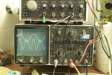
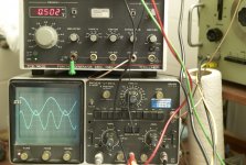
With just a small shift from center I could change the distortion dramatically; turning one way I got 2nd harmonic out of phase and the other way I got the second harmonics in phase - so the crest coincides with the top of the sine going.
I selected it quite a bit higher than Nelson does himself (his example 0,03%); I can't measure that low with that clarity. I choose a lot higher.

left

right

I settled for 0,6% 2nd harmonics, that is -44 dB, at that point the third harmonics is far away and slightly visible for me (I have no sound card). Many well sounding 300B and 2A3 SE amplifiers have this level of -43 dB for 2nd harmonics too. I forgot to check how stable this 'distortion' is.
It is quite well sounding now. So thanks a lot for this implementation idea.
(Compare my 300B PP that has 0,1% 2nd harmonics at 1 watt but that shifts to 0,6% 3rd harmonics at 4 watts and 6% 3rd at 12 watts)
Initially I had matched my 10/100 ohm resistors with great care. Well that was no good idea. It gave low distortion, for sure. But it was a bit hard sounding.
I set up P3 with 47 ohms to both sources and a 100 ohm pot for P3. The resulting source resistance was 8,3 ohms.
With just a small shift from center I could change the distortion dramatically; turning one way I got 2nd harmonic out of phase and the other way I got the second harmonics in phase - so the crest coincides with the top of the sine going.
I selected it quite a bit higher than Nelson does himself (his example 0,03%); I can't measure that low with that clarity. I choose a lot higher.

left

right

I settled for 0,6% 2nd harmonics, that is -44 dB, at that point the third harmonics is far away and slightly visible for me (I have no sound card). Many well sounding 300B and 2A3 SE amplifiers have this level of -43 dB for 2nd harmonics too. I forgot to check how stable this 'distortion' is.
It is quite well sounding now. So thanks a lot for this implementation idea.
(Compare my 300B PP that has 0,1% 2nd harmonics at 1 watt but that shifts to 0,6% 3rd harmonics at 4 watts and 6% 3rd at 12 watts)
Thanks for that got them reversed but no harm time to reverse the matching.Hi,
Patrick suggested higher Idss on the SJ74, not K170.
http://www.diyaudio.com/forums/pass-labs/208880-f5x-euvl-approach-build-thread-2.html#post2947487
Also, this mostly matters only if you plan on using complementary output mosfets like the toshiba's. For the F5/T it's probably easier to use P3 to tune the harmonics (well, that is if you have a scope).
BTW, if you are curve matching, could you post a curve of the sj74? There was some debate about their authenticity in another thread.
Question about Teabag Turbo F-5 W/Tea-bags Boards
When you use Teas boards but are only doing V-2 (two pairs per side)
Do you just install the Fets and associated resistors in the positions you want to use, or is there any jumpering involved, like one would do on the cascode positions if one was not using cascode? I asked this also on the Build thread but havent received any feedback, thought this might be more appropriate?
Thanks,
Russellc
- Home
- Amplifiers
- Pass Labs
- F5 Turbo Builders Thread