I have done some LTSpice simulations of alternative stereo amp grounding here: http://www.diyaudio.com/forums/pass-labs/216616-f6-amplifier-488.html#post3551200. My approach is to attempt to model the resistive (and inductive) elements in the grounding system and the noise source(s) and show how that impacts channel separation and ground system noise.
This subject probably deserves an entire thread by itself.
This subject probably deserves an entire thread by itself.
Some Observation on my current F5T V2?
Input shorted: DC Output offset very stable at +/-1mv most of the time staying on 0mv.
Input connected to tube Pre-amp: No music with DC offset -35mv / with music will vary from 60mv to -30mv.
Input connected to Ipod Touch: No music DC offset -24mv / with music will vary from 10mv to -5mv.
Input connected to laptop: No music DC offset -2mv / with music will vary from 1mv to -2mv.
Any comments on the above results?
Cheers.
Based on the fact that they are all different I suspect it is related to the applied input. Any way to check DC offset on the output of these items. Being direct coupled, if DC is present, then it will affect bias of JFet FE, as it will change the voltage seen at the gate. Could be wrong, perhaps others will have suggestions.
Based on the fact that they are all different I suspect it is related to the applied input. Any way to check DC offset on the output of these items. Being direct coupled, if DC is present, then it will affect bias of JFet FE, as it will change the voltage seen at the gate. Could be wrong, perhaps others will have suggestions.
Is there any circuit, let say a buffer, that can be connected to input FE that could possibly give a stable bias at any given input? Using my Accuphase as benchmark, at any given input they are stable at 0mv DC offset even with playing music....though I dont have experience with other commercial amp if they behave the same.
abadsantos - Your measurements seem normal.Any input I use will vary the output offset a little on my amp.
How does it sound?
Hi Jim,
Thanks.
For the tube pre - it is better connected with the Accuphase.
But for the Laptop and Itouch (w/o any DSP), it seems the Turbo will beat it in all areas from top to bottom.
Do you think the F5T does not have synergy with tubes? or too much gain?
Those variable output offsets tell me each Source has a different output offset. The DC coupled F5 is passing those Source offsets to it's output.Some Observation on my current F5T V2?
Input shorted: DC Output offset very stable at +/-1mv most of the time staying on 0mv.
Input connected to tube Pre-amp: No music with DC offset -35mv / with music will vary from 60mv to -30mv.
Input connected to Ipod Touch: No music DC offset -24mv / with music will vary from 10mv to -5mv.
Input connected to laptop: No music DC offset -2mv / with music will vary from 1mv to -2mv.
Any comments on the above results?
Cheers.
Making some progress...
I thought posting some pictures will be nice.
I'm rebuilding my F5Tv2 to a v3.
One channel is done, think I test it first, before buiding the next channel. Curious if it will be stable with the larger output stage.
I'll test it today, hope I don't destroy it
Made some improvements too.
-Used Kerafol 86/82 red for the outputs and diodes. On the first pic you can see it's rather fragile, can't be used twice. I mounted the outputs for a test with M4 bolds with washer, as tight as possible, and it gives too much pressure in the area of the M4 so it destroys the Kerafol.
So I decided to make a clamping bar of 4 mm steel just for the outputs. See pictures.
Hope the thermal coupling gets better. Will post the results.
- Coupled the Jfets with some copper and thermal glue.
- I glued the new (better) thermistors to the outputs. I have good experience with that, with my standard F5.
- Replaced the 10 Ohm JFet source resistors for Dale CMF55's.
- made the connection to the PSU with faston connectors, so it's easier to disassemble.
- Upgraded the outputs source resistors to 10 Watt with two paralled MPC74 0.47 Ohm resistors. Looks nicer when the whole PCB is filled with components...
- upgraded some cabling with thicker 6mm cable. And for the input no more fragile coax, but twisted signalwire. Like Pa does...
Oh, and I build a DC-filter ( schematic of Rod Elliot) for the mains, see picture, and now all mechanical hum of the big toroids is gone !

Walter, your work looks brilliant. Love the way you have placed the caps in close proximity to the amp board. Any further progress? What boards are you using for the amp and the caps? What transformer output voltage? Why the two paralled 0.47 ohm resistors instead of the 1ohm suggested? Thanks.
Walter, your work looks brilliant. Love the way you have placed the caps in close proximity to the amp board. Any further progress? What boards are you using for the amp and the caps? What transformer output voltage? Why the two paralled 0.47 ohm resistors instead of the 1ohm suggested? Thanks.
Thanks nashbap,
I posted the last pictures of my finished f5T v3 here:
http://www.diyaudio.com/forums/pass-labs/166784-pictures-your-diy-pass-amplifier-209.html
I used the Teabag PSU and AMP boards, he is a member on this forum. So easy to find.
Transformers are 2 x Amplimo 2x25V 2 x 12,5 Ampere. I'm using matched Toshiba 2sk1530 / 2sj201 for output devices and those devices need around 0,22 Ohm for source-resistors. So 2x 0,47 Ohm paralleled.
Walter
Walter, Any further progress? QUOTE]
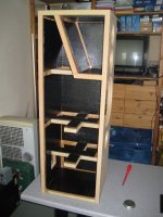
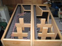
Haha, bit OT but making progress with this:
drivers: Vifa NE123, Vifa NE265 and Scanspeak Illuminator D3004/66200
Attachments
- Home
- Amplifiers
- Pass Labs
- F5 Turbo Builders Thread