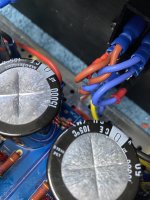
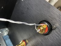
Under each piece of blue heatshrink tubing is a gate stopper resistor. The F5 amp has been running this way for years with no problem. The resistor along with the gate capacitance forms a low pass filter which suppresses any tendency toward oscillation.
Attachments
The extra gain is not because you need it. It is to keep the circuit stable. Read the F5T article and follow the schematic. If you deviate from it and try to take shortcuts you will run into problems.
And yes it's possible to build a front end with the f5 topology. It's been done many times. And even done by Mr. Pass. Check the BA-3 front end (f5 w/no feedback) or the vfet 2 front end. Or EVUL's F5 headphone amp.
Is it possible to use your f5 power amp as a preamp? Yes. But why? It will noisy (compared to a regular preamp) and it's built for current, not voltage. It's not a good choice.
It was just a thought. I've got a pre-amp I'm happy with.
Under each piece of blue heatshrink tubing is a gate stopper resistor. The F5 amp has been running this way for years with no problem. The resistor along with the gate capacitance forms a low pass filter which suppresses any tendency toward oscillation.
I'm going to be making that modification tonight.
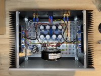
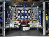
Here's my take on the F5 - it's my first step outside of a straight kit build so I kept it as vanilla as I could. It took me a while to distill all of the help and knowledge from this forum and Papa Pass' website.
Parts selection is suitably over-spec'd as I guess is expected for a novice without an EE background. The transformer is mounted on a galvanised steel timber brace, not how I planned to do it originally, but you gotta make the most of the space you've got.
DC offset is around 20mV at startup and sinks down to 1 or 2mV once things heat up - I feel pretty chuffed at that. Bias is as suggested in the original article at 1.3A.
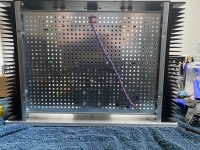
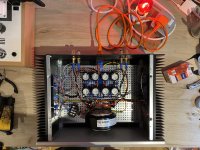
I had a bit of auditable hum with the "old wiring" (first internal shot) but some tips from a nice chap in a chat room, a bit of twisting and re-routing and I'm down to a barely audible hum (second internal shot).
It sounds simply wonderful - super pleased with how things turned out - this site is an amazing resource - thanks to everyone that makes it what it is!
Parts selection is suitably over-spec'd as I guess is expected for a novice without an EE background. The transformer is mounted on a galvanised steel timber brace, not how I planned to do it originally, but you gotta make the most of the space you've got.
DC offset is around 20mV at startup and sinks down to 1 or 2mV once things heat up - I feel pretty chuffed at that. Bias is as suggested in the original article at 1.3A.
I had a bit of auditable hum with the "old wiring" (first internal shot) but some tips from a nice chap in a chat room, a bit of twisting and re-routing and I'm down to a barely audible hum (second internal shot).
It sounds simply wonderful - super pleased with how things turned out - this site is an amazing resource - thanks to everyone that makes it what it is!
Attachments
Last edited:
Here's my take on the F5 - it's my first step outside of a straight kit build so I kept it as vanilla as I could. It took me a while to distill all of the help and knowledge from this forum and Papa Pass' website.
Parts selection is suitably over-spec'd as I guess is expected for a novice without an EE background. The transformer is mounted on a galvanised steel timber brace, not how I planned to do it originally, but you gotta make the most of the space you've got.
DC offset is around 20mV at startup and sinks down to 1 or 2mV once things heat up - I feel pretty chuffed at that. Bias is as suggested in the original article at 1.3A.
I had a bit of auditable hum with the "old wiring" (first internal shot) but some tips from a nice chap in a chat room, a bit of twisting and re-routing and I'm down to a barely audible hum (second internal shot).
It sounds simply wonderful - super pleased with how things turned out - this site is an amazing resource - thanks to everyone that makes it what it is!
Super nice build! If it doesn't get too hot you can try .7V across the source resistors.
heya all, sorry if similar question has been asked before but 16k+ posts is really huge reading material..
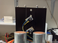
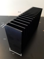
ok, here is the question... will this heatsink be suitable for F5, dimensions are in pic (ofc I plan to use two of them, one for each channel).
tranny I plan to use is 2x17V 300VA, output devices IRFP's.
It will be hooked on B&W685 in cca.20m2 living room...
tnx
ok, here is the question... will this heatsink be suitable for F5, dimensions are in pic (ofc I plan to use two of them, one for each channel).
tranny I plan to use is 2x17V 300VA, output devices IRFP's.
It will be hooked on B&W685 in cca.20m2 living room...
tnx
Attachments
I am having 1 per channel of 300x40x165mm in a 4U case and it gets ~55-60 degree C hot. This: Dissipante 04/300N 4U 10mm NERO
Anything smaller is not enough. + don't forget to flat sand the cooler before attaching the transistors - it makes huge a difference.
Anything smaller is not enough. + don't forget to flat sand the cooler before attaching the transistors - it makes huge a difference.
don't forget to flat sand the cooler before attaching the transistors - it makes huge a difference.
Good tip! Thanks.
Toner Layouts for F5
Hello,
There was a request for F5 Layouts in the Pictures Thread
Pictures of your diy Pass amplifier
I have some made for myself. I would post them here so Ballisticz4 and maybe other Members can use them well too.
But they are very inspired by the original F5 Layouts.
Is it a Problem? Or is this maybe not welcome?
Any recommendations / suggestions?

Looks good Baseonmars,
I would put a rubber grommet or sleeve of some kind around the mains wires where they pass through the bottom plate.
Thanks! I filed the holes smooth but you’re right - better safe than sorry - I’ll put an order in cheers!
The heatsinks are big enough and the power supply.
add a heatsink to the jfets and increase bias far as you can, thus increasing power in class A
- Home
- Amplifiers
- Pass Labs
- F5 power amplifier