My dac have 2V output, in F5 as input have a voltage divider 1/10, because K170 J74 can only handle 200mV input, you can change the the divider for higher input but this will not change the acceptable gain of K170/J74. I think with a preamp you will get more distortion for higher signals of 2V.
My point is to get more headroom from the input stage by changing K170/J74
Please correct me if I am wrong..
The JFETs do not need to handle the full input signal, but just the difference between the input signal and the feedback signal. This difference is much lower. The input stage will not be suffering from dynamic limitations.
I've got a problem... I broke my F5 into monoblocks and as i started biasing one up, it popped it's fuse. I dropped another fuse into it, popped that one immediately.
A little about the amps... They're running 600VA transformers with 24V secondaries so I'm running about 32V rails. I reduced the source resistance down to .28 ohm when I split them up. The one in the original chassis is doing just fine biased at about 1.5 amp. I had the other one biased up around that point when it just took a crap on me. I'm getting a very low resistance between the + and - rails and ground so that seems very problematic. I'm not sure how it could be a bad transistor and i'm not seeing anything obviously amiss. Where would be a good spot to start checking? Any help would be VERY appreciated.
A little about the amps... They're running 600VA transformers with 24V secondaries so I'm running about 32V rails. I reduced the source resistance down to .28 ohm when I split them up. The one in the original chassis is doing just fine biased at about 1.5 amp. I had the other one biased up around that point when it just took a crap on me. I'm getting a very low resistance between the + and - rails and ground so that seems very problematic. I'm not sure how it could be a bad transistor and i'm not seeing anything obviously amiss. Where would be a good spot to start checking? Any help would be VERY appreciated.
Do you read open circuit from hs to center pin of output transistor?
OK... i've pulled the P channel mosfet and i'm getting no continuity to ground from any of the pins. Looking at it with the pins down, I'm getting 10 ohm from the left pin to the middle and right and it's basically a dead short from the middle to the right regardless of where I put the plus probe. I'm also getting a dead short from the output post to ground with the N channel part still in the board. The JFETs seem to be looking ok with about 54Kohm on the gate pin. I'm having that unpleasant feeling I've fried my mosfets.... Is that sounding like the case?
The point was to check if your thermal pad was letting the transistor short to the hs, before you pulled it....
I wasn't getting anything like a short to the chassis on any of the pins before I pulled it. It was about 20 ohm on all the pins on both of them. Should the source and drain measure likes dead shorts, because that's what I'm getting on both of them. And before I pullled the N channel it was showing very low resistance from the output post to ground.
Update: Pretty sure I fried the outputs. I definitely shouldn't be getting a dead short across the drains and sources. Just ordered some more....
I'm a little confused how I fried them though... They were barely hot and well mated to the heat sink. Was I asking too much of them to get 1.5 to 1.6 amp out of them? I had them biased to 1.4 amp on a single heatsink before and they got pretty hot, but these weren't anywhere near hot.
I'm a little confused how I fried them though... They were barely hot and well mated to the heat sink. Was I asking too much of them to get 1.5 to 1.6 amp out of them? I had them biased to 1.4 amp on a single heatsink before and they got pretty hot, but these weren't anywhere near hot.
Possibilities:
- Mosfet touching heatsink
- Thermistor insulation worn away and touching mosfet/heatsink
- PSU wired incorrectly
- Initial bias set too high
- you extended one mosfets leads to reach the other side of the chassis with some wire and now the source and gate resistors are very far away on the other side of the chassis. Which caused it to oscillate and BOOM. THIS IS MY BEST GUESS.
You have a single pair of mosfets for each channel, correct? And you are mounting one N channel mosfet on one sink and one P channel mosfet on the other? This circuit relies on thermal stability between the mosfets. by splitting them on separate sinks you can introduce DC offset and bias hogging. I do not know if this is the issue but it's possible.
F5T with multiple pairs doesn't have this problem when used as mono blocks...since it has N+P mosfet on one heatsink and N+P Mosfet on the other.
Also, why monoblocks with a single pair of mosfets? Not much to be gained, bias-wise. You really need multiple pairs (for the reasons above) to spread the heat and distribute the load among more mosfets.
I'm pretty sure it wasn't touching the heatsink. I readjusted the thermistor so it wasn't touching anything metal. I tested the power supply before i connected the amp and it was looking good. i had the pots rolled all the way back before i powered it up and it was doing fine until i got up around 1.55 amp. I didn't think separate sinks would be an issue since the 5U chassis uses separate sinks for each output. So far that hasn't been an issue with the other one. The biases are extremely stable on that one. It could be oscilation with the long leads
The amp was really too hot in the 4U chassis which was my main reason for going monoblocks with it. I used 18g wire to connect the far side MOSFET feeling that would be less prone to oscillation. I wasn't seeing any significant voltage on the output though.
I've got 5 pairs of MOSFETS on the way. I'm going to see where I get with a new pair and see if I can get my hands on a scope to check into the oscillation.
I appreciate your help. I'll check back in when i can make more progress.
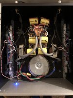
It is the long leads to the mosfet. Please post a pic.
This will eventually destroy your speakers. Do not use the amplifier like this even if it does bias up. You need to move gate resistor to the mosfet pin.

It's the braided black wires running beneath the power supply.
I do have a frequency counter on my DMM that reads up to 4MHz and I'm getting all zeros on the one that's biased up and running right now. It's got nothing connected to it. If the insurance against oscillation is as simple as moving the resistor, that's simple, cheap insurance. It should be easy to tie the gate wire to a bolt in the heat sink and run the resistor to the gate.
View attachment 827605
It's the braided black wires running beneath the power supply.
I do have a frequency counter on my DMM that reads up to 4MHz and I'm getting all zeros on the one that's biased up and running right now. It's got nothing connected to it. If the insurance against oscillation is as simple as moving the resistor, that's simple, cheap insurance. It should be easy to tie the gate wire to a bolt in the heat sink and run the resistor to the gate.
Gate resistor needs to be as close as possible to mosfet.
It controls the mosfet...The long wire with the gate resistor far away is like trying to drive a car with the gas pedal connected by a rubber band. It's not gonna provide precise and timely control.
The amp might be stable while idling but apply some signal to it and I bet the other amp will pop too. If you do a little research in this thread others have had this same experience. Others experimenting with flying mosfet leads have destroyed speakers. Fortunately I read about it before I did mine. You can see the flying mosfet with gate resistor attached in lower left. This is an F5 pcb with dual pairs of mosfets per channel.
Regarding the N and P Mosfets on different sinks I wouldn't do it. There really is not a lot of advantage bias wise and you are asking for DC offset fluctuations. On the 5 U chassis the sinks are split but they are thermally in contact. Your dangerous situation would be if one sink was closer to a window/wall or something and one was not or if something was to obstruct one sink and not the other it will introduce DC offset due to the imbalance.
At the very least please keep an eye on the DC offset. I am trying to save your speakers.
Personally, I think the best idea is to just install 2 pairs per channel now. Preferably using the f5T pcbs. No more flying leads and you can cascode the jfets. And you will be able to get probably 2.5A bias out of it and it will sound much better.
Attachments
Last edited:
I wouldn't be at all opposed to adding another pair of MOSFETs, but I'm not sure where I'd get matched pairs. I'm very conscious of the heat issue with the sinks and I will make sure they're stable for a day at least before I connect speakers to them. I have no vents or windows near where they will be and the room hardly varies in temperature. The one has been stable for about 7 hours today so I'm feeling mostly good about it. I will definitely be moving those resistors before turning them back on. I appreciate all the input and advice. If you have a lead on the matched MOSFETs to do as you suggest, I'd probably buy them. I really like your amp!
I wouldn't be at all opposed to adding another pair of MOSFETs, but I'm not sure where I'd get matched pairs. I'm very conscious of the heat issue with the sinks and I will make sure they're stable for a day at least before I connect speakers to them. I have no vents or windows near where they will be and the room hardly varies in temperature. The one has been stable for about 7 hours today so I'm feeling mostly good about it. I will definitely be moving those resistors before turning them back on. I appreciate all the input and advice. If you have a lead on the matched MOSFETs to do as you suggest, I'd probably buy them. I really like your amp!
Buy from mouser and match them yourself. You can get 20 mosfets for $40. Nelson has an article on how to match them. If you are lucky, they will all be from the same tube and same batch and pretty much be matched out of the package. You don’t need to match N to P. Just N to N and P to P. And you don’t need to match them channel to channel.
But be aware you need to increase source resistor wattage to 6 watts (2x 3 watt resistors) and also increase feedback resistor wattage and values. It’s all in the F5 turbo article.
Or buy from NicMac here: IRFP240/9240 - Google Drive
I already have 2 3W resistors in parallel at the source and 5 watt feedback resistors the F5T article describes. I'm assuming I can run the pair off the same source resistors. I looked at Mouser and Digikey for them and they're both old out of both. I'll see if I can match up some of the parts I'm getting.
I already have 2 3W resistors in parallel at the source and 5 watt feedback resistors the F5T article describes. I'm assuming I can run the pair off the same source resistors. I looked at Mouser and Digikey for them and they're both old out of both. I'll see if I can match up some of the parts I'm getting.
Each mosfet must have its own source resistor. Feedback resistor values are different in f5T. Less feedback, more gain. Follow the f5T schematic closely. Your speakers will appreciate it.
I really don't need more gain out of these things. I was just laid off work last week so I'm going to need to wait on a total upgrade to the F5T, but you've convinced me that's the way to go. It looks like NicMac's matching is well beyond anything I could pull off and so well worth the price he's asking. That's something I could do in the near term.
This might seem like a weird question, but is it possible to modify the F5 to use as a pre-amp like has been done with the BAGS complimentary gain stage?
Again, I really appreciate the help and advice here. Thank you.
This might seem like a weird question, but is it possible to modify the F5 to use as a pre-amp like has been done with the BAGS complimentary gain stage?
Again, I really appreciate the help and advice here. Thank you.
I really don't need more gain out of these things. I was just laid off work last week so I'm going to need to wait on a total upgrade to the F5T, but you've convinced me that's the way to go. It looks like NicMac's matching is well beyond anything I could pull off and so well worth the price he's asking. That's something I could do in the near term.
This might seem like a weird question, but is it possible to modify the F5 to use as a pre-amp like has been done with the BAGS complimentary gain stage?
Again, I really appreciate the help and advice here. Thank you.
The extra gain is not because you need it. It is to keep the circuit stable. Read the F5T article and follow the schematic. If you deviate from it and try to take shortcuts you will run into problems.
And yes it's possible to build a front end with the f5 topology. It's been done many times. And even done by Mr. Pass. Check the BA-3 front end (f5 w/no feedback) or the vfet 2 front end. Or EVUL's F5 headphone amp.
Is it possible to use your f5 power amp as a preamp? Yes. But why? It will noisy (compared to a regular preamp) and it's built for current, not voltage. It's not a good choice.
- Home
- Amplifiers
- Pass Labs
- F5 power amplifier