The 10 ohm resistor has to handle quite a lot of power. With a 0.4W resistor you want to keep peak dissipation below about 200mW.
Actual possible Pd of part at 20Vp output is exactly 1 watt. Desired rating is therefore about 2W (at 50% Pd the case of the resistor will be between 80 and 100C, and high temperatures shorten part life).
This means with allowable max of 200mW you can have about 9Vp on output, or just about five watts of usable output power. Still enough for a high sensitivity speaker system, but you'll burn that resistor if you push the amp harder.
I've had to repair some DIY implementations that originally used a 1/4w Dale resistor in that position - every single one of them were burnt to a crisp in less than a year. The output MOSFETs and JFETs were toasted, and one poor fellow burned out his woofer coils as well.
Are there really 1W recommend? I have used 1/4W in that position. Do i have to Change them for reliability of the amp? (It is the standart f5 without P3)
It's really your choice, you can crunch the numbers yourself and work out what you're comfortable with.
A maximum of 20V can appear across the combination of 50R and 10R, in exactly the proportion of 50:10. The resultant power dissipation is (V^2)/R, which is 1.1 watt. For safety's sake I never use less than 2W resistors here, and at lower dissipation resistors tend to have lower noise and distortion as well.
A maximum of 20V can appear across the combination of 50R and 10R, in exactly the proportion of 50:10. The resultant power dissipation is (V^2)/R, which is 1.1 watt. For safety's sake I never use less than 2W resistors here, and at lower dissipation resistors tend to have lower noise and distortion as well.
Last edited:
Are there really 1W recommend? I have used 1/4W in that position. Do i have to Change them for reliability of the amp? (It is the standart f5 without P3)
I've never seen an F5 BOM with anything less than 1/2W throughout. I've used 1/4W in phono stages, but not in an amp.
Nelson himself says 1/4w is fine in his article in AudioExpress a jillion years ago.
You can DIY! The F5 Power Amplifier | audioXpress
You can DIY! The F5 Power Amplifier | audioXpress
As ZM would say, "Fugly!"

What is ugly huge heatsink/case or fancy components?
I guess i like overkill.
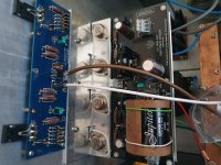
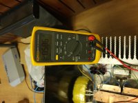
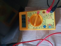
I started bias left channel.
I am in the midde of bias, The heatsink is not heat up maybe because of it is huge.
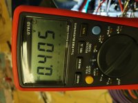
And second speaker bindings go high as 0.3v instead of 0.1v as written in the guide here.
What could be wrong any idea?
I am in the midde of bias, The heatsink is not heat up maybe because of it is huge.
And second speaker bindings go high as 0.3v instead of 0.1v as written in the guide here.
What could be wrong any idea?
Attachments
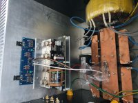
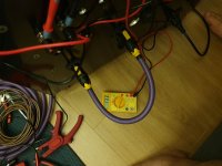
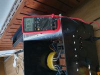
After couple of hours waiting it only warm a little bit.
I guess i néed much smaller heatsink.
Btw voltage drop 21.6 from 23v under load in clc setup
I guess i néed much smaller heatsink.
Btw voltage drop 21.6 from 23v under load in clc setup
Attachments
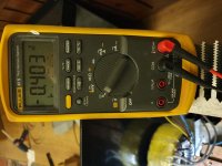
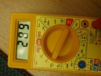
Thanks Dennis, But i already reach the 0.59v.and still 130mv. Is there a risk to damage componenents if i go Beyond 0.59v? What is the limit i have stop or is there any oyher way to debug and see whats is wrong with it?It's good to have a large heatsink.
You should reduce your dc offset by adjusting P1/P2.
Thanks Dennis, But i already reach the 0.59v.and still 130mv. Is there a risk to damage componenents if i go Beyond 0.59v? What is the limit i have stop or is there any oyher way to debug and see whats is wrong with it?
Reduce the voltage on P1 and see if the offset goes down.
Last edited:
The limit for bias is 65C on pin 1. You seem to have large heatsinks, which is good. Going a bit above 0.6v is not going to cause any problems.
As others suggest, adjust bias as required to get DC offset as close to zero as possible. This may result in the two mosfet having slightly different bias voltages, which is normal as Vgs varies greatly from the P channel to the N channel
As others suggest, adjust bias as required to get DC offset as close to zero as possible. This may result in the two mosfet having slightly different bias voltages, which is normal as Vgs varies greatly from the P channel to the N channel
While Postip works on his biasing, has anyone tailored the current limiting in their F5 to their speaker load?
Nelson's article calculates 150 ohms for R19 with 1K at R17, in order for Q5 to see .6v when there is 4.7v and 10 amps across R11.
I tried some different values for R19 in the calculator Voltage Divider Calculator. If I wanted to hard limit at 5 amps for my 4 ohm speakers, that's 2.35v across R11, to divide that down to .6v it would take 345 ohms at R19.
What is confusing to me is the "stock" value of R19 is 100 ohms, which means it's not hard limiting until 14 amps/6.6v across R11. Am I calculating correctly?
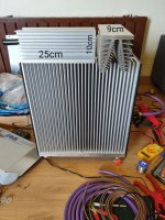
You can never have too much heat sink.
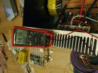
Well then i need replacement here. I have this 2 heatsink on top of current in stock.
Are they enough or i have to cut the main one into small size.
Attachments
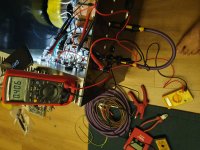
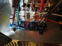
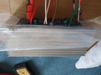
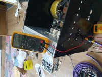
Well i tried with small heatsink. I guess i did it. I realized also and want to write here for the newbies like me.
P2 and p1 doesnt have to have same turn. Only this way i can achive the expexted results. I thought lets say if i half turned p1 also i need tho half turn p2. But it is completely wrong.
The only issue is i can not touch heatsink wih bare hand more than 1-2 second. But afer assembly whole case with the rest of case parts which will be aluminum also i guess i will be not a big issue.
Thank you all for help folks.
Attachments
Last edited:
Well i tried with small heatsink. I guess i did it. I realized also and want to write here for the newbies like me.
P2 and p1 doent have to have same turn. Only this way i can achive the expexted results. I thought lets say if i half turned p1 also i need tho half turn p2. But it is completely wrong.
The only issue is i can not touch heatsink wih bare hand more than 1-2 second. But afer assembly whole case with the rest of case parts which will be aluminum also i guess i will be not a big issue.
Thank you all for help folks.
Congrats! Do you have an infrared thermometer? It's very useful to know the temp of the heatsink and the mosfet bodies.
- Home
- Amplifiers
- Pass Labs
- F5 power amplifier