Hello;
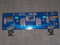
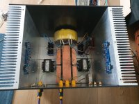
Due to i quit my job Finally i have a time to complete my f5 amplifier. Yesterday i completed soldering and i have few questions and need help. I have v3 board btw. Please see attached pictures.
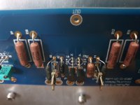
1. Do i have to solder led and led resistor or can i keep it as blank.
2. Is it fine to use 0.4w rated chardof zfoil 10ohm resistor for r3 and r4. Or i need to desolder and solder minimum 1watt.
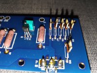
3. Q1 N-Channel JFET Input 2SK170
Q2 P-Channel JFET Input 2SJ74
Did i soldered their direction wrong? Currently flat faces touching but i guess round faces should touch?
Due to i quit my job Finally i have a time to complete my f5 amplifier. Yesterday i completed soldering and i have few questions and need help. I have v3 board btw. Please see attached pictures.
1. Do i have to solder led and led resistor or can i keep it as blank.
2. Is it fine to use 0.4w rated chardof zfoil 10ohm resistor for r3 and r4. Or i need to desolder and solder minimum 1watt.
3. Q1 N-Channel JFET Input 2SK170
Q2 P-Channel JFET Input 2SJ74
Did i soldered their direction wrong? Currently flat faces touching but i guess round faces should touch?
Attachments
Last edited:
2. Is it fine to use 0.4w rated chardof zfoil 10ohm resistor for r3 and r4. Or i need to desolder and solder minimum 1watt.
The 10 ohm resistor has to handle quite a lot of power. With a 0.4W resistor you want to keep peak dissipation below about 200mW.
Actual possible Pd of part at 20Vp output is exactly 1 watt. Desired rating is therefore about 2W (at 50% Pd the case of the resistor will be between 80 and 100C, and high temperatures shorten part life).
This means with allowable max of 200mW you can have about 9Vp on output, or just about five watts of usable output power. Still enough for a high sensitivity speaker system, but you'll burn that resistor if you push the amp harder.
I've had to repair some DIY implementations that originally used a 1/4w Dale resistor in that position - every single one of them were burnt to a crisp in less than a year. The output MOSFETs and JFETs were toasted, and one poor fellow burned out his woofer coils as well.
The BOM I have recommends 1W for these, and checking mine I have 1/2W in my build. There's no noticeable scorching on them but I ordered some 2W replacements to be safe.
Wow thanks for fast response guys.
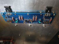
I add 1watt ones into free slots as addition.
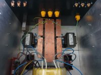
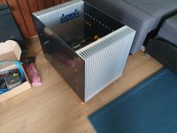
I am planning to put 3 different amplifier in same case so f5 is the first one jhl 2003 will be second (which is ready) and third one i did not decided yet.
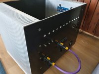
I make a fast progress and completed power soft start + CLC. side today. If i have enough time i will complated low voltage cabling tomorrow.
I appreciated if have any comments to improve it.
I add 1watt ones into free slots as addition.
I am planning to put 3 different amplifier in same case so f5 is the first one jhl 2003 will be second (which is ready) and third one i did not decided yet.
I make a fast progress and completed power soft start + CLC. side today. If i have enough time i will complated low voltage cabling tomorrow.
I appreciated if have any comments to improve it.
Attachments
-
 20190715_181320_compress60.jpg287.7 KB · Views: 229
 -
 20190715_181242_compress90.jpg269.9 KB · Views: 223
 -
 20190715_181234_compress1.jpg361 KB · Views: 222
 -
 20190715_181212_compress18.jpg197.9 KB · Views: 218
 -
 20190715_181159_compress32.jpg256.3 KB · Views: 456
 -
 20190715_181147_compress43.jpg386.1 KB · Views: 511
Wow thanks for fast response guys.
I add 1watt ones into free slots as addition.
I am planning to put 3 different amplifier in same case so f5 is the first one jhl 2003 will be second (which is ready) and third one i did not decided yet.
I make a fast progress and completed power soft start + CLC. side today. If i have enough time i will complated low voltage cabling tomorrow.
I appreciated if have any comments to improve it.
The parallel ones you have added changes the circuit, ie two 10R in parallel gives 5R resulting in different gain.
Hammond Inductors
I see Newark has these inductors (Hammond 195J10) on sale for $23.71 each (normally $78.99.) My shipping cost (16 pounds) in USA was $26.78 for a Total of $77.05 with $2.68 tax, for a pair of 10 amp, 10mH, 0.07 DCR inductors.
Pretty sweet!
Look up by googling part number, or: https://www.newark.com/hammond/195j...=195J10&ddkey=https:en-US/Element14_US/search
Rush
What are they used for?
What are they used for?
Potstip used them in CLC F5. See his pictures.
These can be used on F5 Turbo, or another First Watt type amp.
Rush.
Wow thanks for fast response guys.
I add 1watt ones into free slots as addition.
I am planning to put 3 different amplifier in same case so f5 is the first one jhl 2003 will be second (which is ready) and third one i did not decided yet.
I make a fast progress and completed power soft start + CLC. side today. If i have enough time i will complated low voltage cabling tomorrow.
I appreciated if have any comments to improve it.
Adding 10R in parallel at R4 and R3 will result in 5R combined and also the wattage rating will be the same as the lowest rated resistor...so, take out the Z foils at R4 and R3.
Also, you have used your Z foils mostly on the current limiting portion of the amplifier...nothing wrong with that but those resistors will never impact audio quality unless the current limiting activates, which won't sound good anyways.
Critical resistor positions are R1, R3/R4, R13/14 (you have Z foils here) and feedback and source resistors which need 3 watt resistors, so no z foils there.
I was told that low value resistors don't have much impact on the sound quality. Using Z-foils may have no real benefit in this circuit.
It totally depends on the function of the resistor in the circuit...not the value. And in a simple, low-parts count amplifier like this every resistor (with the exception of the current limiting circuit) is doing something important.
It totally depends on the function of the resistor in the circuit...not the value. And in a simple, low-parts count amplifier like this every resistor (with the exception of the current limiting circuit) is doing something important.
I was going to change the resistors in my SET amps to Z-foils which are very simple. The designer (who is very reputable) told me not to spend the money.
I was going to change the resistors in my SET amps to Z-foils which are very simple. The designer (who is very reputable) told me not to spend the money.
“Worth the money” is subjective and depends on how much money you have. Tube amp guys routinely put carbon comp resistors in amps to “flavor” them.
I have never used z foils. PRP and Dale are good enough for me. If you want to throw money at an F5 I think caps and heatsinks are the two best places. Or Toshiba outputs.
“Worth the money” is subjective and depends on how much money you have. Tube amp guys routinely put carbon comp resistors in amps to “flavor” them.
Depends on the value. I wasn't trying to say it wasn't worth the money. Just that I was told low resistor values make hardly any difference in the sound.
I have never used z foils. PRP and Dale are good enough for me. If you want to throw money at an F5 I think caps and heatsinks are the two best places. Or Toshiba outputs.
I thought Nelson preferred the Fairchild outputs in the F5?
Depends on the value. I wasn't trying to say it wasn't worth the money. Just that I was told low resistor values make hardly any difference in the sound.
I thought Nelson preferred the Fairchild outputs in the F5?
I think Nelson preferred to use mosfets that were being manufactured and available at the time, which the Fairchild’s were.
Now they are out of production so IRFs are the common choice.
The Toshiba vertical mosfets are no longer in production, expensive and hard to find.
I have used all 3 types. I think I prefer the Toshiba but obviously it’s impossible to A/B test them at the same time. But the Toshibas were the most expensive, so they must be the best! That’s a joke. Kind of.
The XA series uses IRF parts.
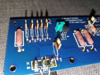
Thanks Hikari1 and cviller i removed 10ohm zfoils.
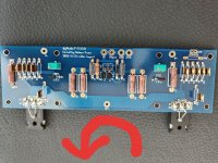
I am planing to bias it today. Bias procedure starts with.
"Please make absolutely sure that all variable resistors P1 and P2 are turned fully counter-clockwise."
But direction is chande depends on which side you look the board. The one that i showed on the picture is correct?
I am planing to bias it today. Bias procedure starts with.
"Please make absolutely sure that all variable resistors P1 and P2 are turned fully counter-clockwise."
But direction is chande depends on which side you look the board. The one that i showed on the picture is correct?
Attachments
Papa mentioned Toshibas recently:
https://www.diyaudio.com/forums/pass-labs/121228-f5-power-amplifier-1602.html#post5807770
https://www.diyaudio.com/forums/pass-labs/121228-f5-power-amplifier-1602.html#post5807770
- Home
- Amplifiers
- Pass Labs
- F5 power amplifier