A single CL60 gives too low a value of added resistance for use on most 230Vac transformer.It could be the soft start board - best to use CL60...
CL60 works for many sizes of 115Vac transformers.
Two series connected CL60, or select a higher resistance NTC, for 230Vac duty.
A single CL60 gives too low a value of added resistance for use on most 230Vac transformer.
CL60 works for many sizes of 115Vac transformers.
Two series connected CL60, or select a higher resistance NTC, for 230Vac duty.
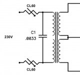
Is it ok to have 2 CL60 in series with transformer mains;
One on phase, brown, before entering xformer;
The second one, on neutral blue, on the other lead of xformer ?
I think they might form another hf filter, in combination with the 0.0033u line capacitor, which is in parallel with xformer primary winding
Thanks,
nAr
Ok, so i used 2 CL60 (although there is only one in the main line of the PSU in the F5 manual?).
I removed amp boards and checked the voltage of the psu under load. Indeed it "breaks in" a little bit, but not like the behavior i can measure with the amp boards.
So here are the values i measured, where Vr is the voltage accross one of the resistors that have 0.5Ohms of the CRC bank:
load: 180 Ohms: V+: 23.4V, Vr: 17mV || V-: 23.5V, Vr: 17.5mV
load: 90 Ohms: V+: 22,8V, Vr: 32VmV || V-: 22,8V, Vr: 32mV
load: 45 Ohms: V+: 21V, Vr: 60mV || V-: 21V, Vr: 60mV
According to my calculation, for example in the case of 180Ohms the load current is 24V/180Ohm = 133mA. I measure 17mV at one CRC-Resistor. I have 4 in parallel results in 0.125Ohms. This leads to a current of 17mV/0.125Ohm = 136mA. That sounds good?
So, i hope those results tell me that my psu is working correctly, am i right?
Attachments
So here are the values i measured, where Vr is the voltage accross one of the resistors that have 0.5Ohms of the CRC bank:
load: 180 Ohms: V+: 23.4V, Vr: 17mV || V-: 23.5V, Vr: 17.5mV
load: 90 Ohms: V+: 22,8V, Vr: 32VmV || V-: 22,8V, Vr: 32mV
load: 45 Ohms: V+: 21V, Vr: 60mV || V-: 21V, Vr: 60mV
According to my calculation, for example in the case of 180Ohms the load current is 24V/180Ohm = 133mA. I measure 17mV at one CRC-Resistor. I have 4 in parallel results in 0.125Ohms. This leads to a current of 17mV/0.125Ohm = 136mA. That sounds good?
So, i hope those results tell me that my psu is working correctly, am i right?
I'm not sure. Consider the 45 ohm load case. Your rail has already
dropped to 21V (from 24 or so with no load). This gives a current
of about 21/45 ~ 0.466A (From Vr , 60mV/0.125ohm = 0.48A). Now a
single channel of F5 at the standard bias will draw about 1.3A, which is
almost 3x the current in your 45ohm test. If this trend on your PS
continues, the voltage will drop significantly more.

ok, shame on me,... i just realized i did the tests with the lightbulb tester... without i am back to 24V with a 45Ohm load
and before i say something more, i try another test with increasing the values of P1 and P2... Furthermore i just checked one of the mosfets looks good...
and before i say something more, i try another test with increasing the values of P1 and P2... Furthermore i just checked one of the mosfets looks good...
i am back to 24V with a 45Ohm load
OK...much better. Take it easy with P1 and P2 and hopefully all will be well.
Good luck.
Cheers,
Dennis
OK...much better. Take it easy with P1 and P2 and hopefully all will be well.
Good luck.
Cheers,
Dennis
ok, let's play sherlock holmes:
yesterday I was worried because of a buzz I heard and I removed the soft start board. Using the light bulb tester and a CL60 in the mains I turned on the amp. WITHOUT removing the light bulb I measured the output offset which was far away from good. Getting nervous i added the softstart board againg thinking I connected something wrong, again WITH the light bulb. Not thinking before writing I got nervous because the offset was still far away from zero and the voltage rails dropped down. Just this moment before when i wanted to write what could have happend to my PSU i realized my mistake...
I was able to adjust to 140mV across the source resistor with zero offset and no voltage drop of the PSU. 24h later of crying and swearing i am back in the business! Thank you very much dennis, you helped through this bad time!
So I think i will leave the softstart board where it is, I add 2 CL60 and I am happy with that. I will go back to the power up procedure now and will tell later if i still hear the buzzing sound...
Happy to hear you appear to have things under control.
I'm a bit confused if you currently have the softstart in place along with the
termistors. (Just a bit worried because in an earlier post you said one of the
caps on the softstart was bulging.)
Please let us know how things go.
Cheers,
Dennis
I'm a bit confused if you currently have the softstart in place along with the
termistors. (Just a bit worried because in an earlier post you said one of the
caps on the softstart was bulging.)
Please let us know how things go.
Cheers,
Dennis
So, at the moment i am not using the soft start board because of this strange elko, i am not sure why this happened? Its the 50V 1000uF. Maybe it was to hot?
Actually i have another question. Until now I used the LED on the soft start board as indicator if the amp is turned on (so the LED is sitting at the front...). Now I think i might use the solder points of the LED on the V3 Board of the F5 layouts. should I add the LED on the other board as well due to symmetry?
Actually i have another question. Until now I used the LED on the soft start board as indicator if the amp is turned on (so the LED is sitting at the front...). Now I think i might use the solder points of the LED on the V3 Board of the F5 layouts. should I add the LED on the other board as well due to symmetry?
Or another possibility (independent of LEDs on the F5 boards) is to wire
a front panel LED from your power supply.
Cheers,
Dennis
Like this.
Inner LEDs are power supply
outers are amp boards.
Attachments

the way you have shown the two CL60 is correct. They are in series and that will work.... So, this wouldn't do the job ?
Best,
nAr
But I don't like that one CL60 is at a different Line voltage from the other.
Officially and technically both CL60 are mains and thus both must be considered Live even when one is actually in the Neutral line.
I would prefer in my own build to have both Cl60 (or resistors) either in the Live line, or in the Neutral line. Not mixed.
Hey!
So today i finally (re)started powering up the F5. I still have a question concerning the power supply. So at the moment I started with around 480mV on both sides. Offset adjusted to zero. During warm up process, so getting into thermal equilibrium, I notice that the voltage across the source resistors slowly drops down, to around 440mV. Offset is still quite constant, its 1mV now. Furthermore the Voltage rails go down to around 22.3V...
Is this normal? When yes, is this due to the thermistors TH1 and TH2? I would just like to understand this... Dennis already mentioned that it's ok when the PSU breaks in a little bit, now I am already at 1A bias, so is this "a little bit"...
Thank you very much! All the best,
Philip
The cold Thermistor has a high resistance (if it's an NTC type)
This has the effect of allowing through a particular value of output bias current.
As the heatsink and output devices warm up, the Thermistor resistance decreases.
This reduces the bias current.
i.e. the cold bias is higher than the final bias.
But there is another temperature induced effect.
As the output devices warm up their Vgs decreases.
This has the effect of increasing the bias current.
When the output device Vgs effect is combined with the Thermistor NTC effect, you find that the bias stays nearly constant.
Depending on the proportional effect of these two nearly cancelling adjustments you could end up with cold bias = hot bias, or cold bias decreases slightly to become a lower hot bias, or cold bias increases slightly to become a higher hot bias.
Once the amplifier is fully warmed up and ignoring the bias and temperature effects during warm up. you will find that at a particular Ta the amplifier will always be at the same bias and the same temperatures.
As the seasons change and/or the room heating/cooling changes the Ta, you will find that the amplifier temperature may not track exactly with Ta. i.e. the room becomes hotter during the summer by 8C degrees, but the amplifier becomes warmer by only 4C degrees. This is the effect of the operating condition temperature compensation being slightly overcompensated. This operating temperature compensation can be different from, even opposite to, the warming up effects.
I prefer a slightly over compensated Tempco to keep the summer time dissipation a bit away from Thermal runaway.
This has no adverse consequence for any mosFET output stage and for any ClassA output stage.
There is a good argument that an optimally biased ClassAB BJT output stage to be very slightly under compensated to increase the Vbias to keep the K referenced temperature Vbias constant (i.e. The absolute temperature bias adjustment).
Last edited:
Thanks andrew for this detailed description!
Still I am not sure what this should tell me. Normally the two effects would cancel each other, thus the current should stay nearly constant.
When i powered up the F5 I adjusted to 480mV, and it went down to 430mV but stayed there constant after two hours. Now i went up to 540mV and it went down to 520mV. (by the way, PSU rails stay at 22.3V so I think thats ok...)
So when it says i should go up to 600mV, this does mean at thermal equilibrium, right? So, i go up to 600, measure after 1-2 hours, it will have gone down and I increase again to 600. i repeat this procedure until its constant at 600mV finally, right?
yes, close in on your chosen setting when the amplifier is full hot and with the case fully assembled. Air flows inside can have an effect.
Then you might want to check what it does when ambient air temperature is high as during high summer. If it goes down rather than up then it should be safe to leave unattended for extended periods, like going to dinner but leaving it playing in another room.
Heatsink switches to detect and alarm on overtemp are handy. Instead of alarm, they could switch off, or just disconnect the speakers.
- Home
- Amplifiers
- Pass Labs
- F5 power amplifier