Lowering both bias and power suply on F5.
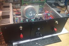
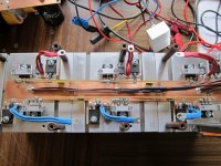
Due to a small heatsink I have built a "baby" vertion of F5 with one pair of FET. I use a smaller transformer with 2x15 V AC. To keep the teprature on "the right side" the bias is 0.8 A (0.4 V). My question is; will this changes influence on the measurement and difference from and ordinare F5 ( likeTHD....). Gain resitors are 220 ohm. Intention is to use it together with a sensitiv horn driver.
Eivind S
Attachments
Last edited:
Lowering both bias and power suply on F5.
Due to a small heatsink I have built a "baby" vertion of F5 with one pair of FET. I use a smaller transformer with 2x15 V AC. To keep the teprature on "the right side" the bias is 0.8 A (0.4 V). My question is; will this changes influence on the measurement and difference from and ordinare F5 ( likeTHD....). Gain resitors are 220 ohm. Intention is to use it together with a sensitiv horn driver.
Eivind S
At a fraction of a watt driving those horns, it will probably be ok.
If your lower bias F5 stays within it's ClassA current limit whenever the speaker demands it's worst case current then I cannot see any drawback.
If you do need very little power, then you may be able to reduce the gain. This will reduce the noise and reduced noise could be important when using a very sensitive speaker.
If you do need very little power, then you may be able to reduce the gain. This will reduce the noise and reduced noise could be important when using a very sensitive speaker.
But very interesting issue for me; will there be any measurable drewbacks with the lower power and the low bias??
Eivind S
Without actually doing that comparison, it's not easy to say, how audible any difference might be.
Lower volts and lower bias means higher distortion but I doubt those horns will ever see more than 1 Watt, so probably not worth losing sleep over.
Nelson published a graph which showed THD versus bias current:
https://passlabs.com/articles/leaving-class-a
It's halfway down the page...
https://passlabs.com/articles/leaving-class-a
It's halfway down the page...
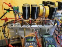
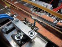
I experimented my F5 with lateral mosfet today. I basically replaced IRFP240/IRFP9240 with 2SK2221/2SJ352, and reduced the source resistor to 0R22. I did not thermally couple 4.7k thermistors with output devices, but the bias was very stable at 0.6-0.8 A.
I don't have THD meter nor reference level speaker system and listening room, but I thought the sound was very good.
What did I miss here?
I don't have THD meter nor reference level speaker system and listening room, but I thought the sound was very good.
What did I miss here?
I got to know about Selectronics Profet amp, which uses k170/j74 jfets for intput and k1058/j162 lateral mosfets for output. So I think basically I converted F5 into Profet, since they use same rail voltage (+/- 24V). Honestly, I cannot tell the difference in sound by my bronze ears.
Hi there,
just tested my F5TurboV2, no problems, both channels working well, at least initially.
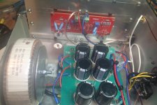
Channel configuration: rails 141mF+1mH CLC, +/-32V, 3x IRFP240/IRFP9140 at 0,7A bias each, heatsinks 45°C after some minutes, no oscillations (at least i didn´t see on scope)
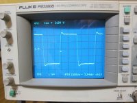
When testing one channel with a 100kHz square wave at 4Vpp (no load on output), it developed 1,7V offset on the output after some ten seconds, but no smoke or heavy current draw.
Result:
One IRFP240 defective, Rgs=230Ohm, Rds=50Ohm
One IRFP910 defective, Rgs=5,9kOhm, Rds=1,1kOhm
Resistances on the other two IRFP9140 were in upper MegOhm range, looks like slight damage too. Other two IRFP240 measured OK.
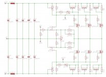
I initially thought i had a mistake on NTC connection, in F5 article they are connected to +/- rail voltages, but in F5Turbo they are connected to Source/Source resistor.
So i wonder what happened here ? I have no clue so far, maybe someone can shed some light on this ?
Definetly don´t want to fry my speakers because of some stupid mistake.
Thanks
Norb
just tested my F5TurboV2, no problems, both channels working well, at least initially.
Channel configuration: rails 141mF+1mH CLC, +/-32V, 3x IRFP240/IRFP9140 at 0,7A bias each, heatsinks 45°C after some minutes, no oscillations (at least i didn´t see on scope)
When testing one channel with a 100kHz square wave at 4Vpp (no load on output), it developed 1,7V offset on the output after some ten seconds, but no smoke or heavy current draw.
Result:
One IRFP240 defective, Rgs=230Ohm, Rds=50Ohm
One IRFP910 defective, Rgs=5,9kOhm, Rds=1,1kOhm
Resistances on the other two IRFP9140 were in upper MegOhm range, looks like slight damage too. Other two IRFP240 measured OK.
I initially thought i had a mistake on NTC connection, in F5 article they are connected to +/- rail voltages, but in F5Turbo they are connected to Source/Source resistor.
So i wonder what happened here ? I have no clue so far, maybe someone can shed some light on this ?
Definetly don´t want to fry my speakers because of some stupid mistake.
Thanks
Norb
Attachments
I got to know about Selectronics Profet amp, which uses k170/j74 jfets for intput and k1058/j162 lateral mosfets for output. So I think basically I converted F5 into Profet, since they use same rail voltage (+/- 24V). Honestly, I cannot tell the difference in sound by my bronze ears.
F5 with lateral mosfet (with same bias current ) has probably about 8 to 10 times lower damping factor than F5 with vertical mosfet. Depending on your speaker (or your ears
") ) the difference may not show clearly but it really does on some speakers mostly on the bass frequency....
) the difference may not show clearly but it really does on some speakers mostly on the bass frequency....Fab
Hi there,
just tested my F5TurboV2, no problems, both channels working well, at least initially.
Channel configuration: rails 141mF+1mH CLC, +/-32V, 3x IRFP240/IRFP9140 at 0,7A bias each, heatsinks 45°C after some minutes, no oscillations (at least i didn´t see on scope)
When testing one channel with a 100kHz square wave at 4Vpp (no load on output), it developed 1,7V offset on the output after some ten seconds, but no smoke or heavy current draw.
Result:
One IRFP240 defective, Rgs=230Ohm, Rds=50Ohm
One IRFP910 defective, Rgs=5,9kOhm, Rds=1,1kOhm
Resistances on the other two IRFP9140 were in upper MegOhm range, looks like slight damage too. Other two IRFP240 measured OK.
I initially thought i had a mistake on NTC connection, in F5 article they are connected to +/- rail voltages, but in F5Turbo they are connected to Source/Source resistor.
So i wonder what happened here ? I have no clue so far, maybe someone can shed some light on this ?
Definetly don´t want to fry my speakers because of some stupid mistake.
Thanks
Norb
Why did you decide to use irfp9140 instead of irfp9240?
DC offset probably shifted as one mosfet failed.
1) Where did you buy your mosfets from?
2) Were they closely matched ie N to N to N and P to P to P (not saying they need to match N to P)
3) What are you using in terms of thermal pads
If they are not matched well, one of the mosfets will start to hog current then the diode connected to that mosfet will start turning on then the mosfet may hog current all the way to destruction.
Last edited:
as ilimzn pointed many times , 240 and 9140 are pretty close brothers
at least closer than 240/9240
Yeah thought that might of been the case.
Symmetry doesnt interest me, hence the reason for not taking notice of that chit chat.
Last edited:
Why did you decide to use irfp9140 instead of irfp9240?
I compared obtainable FETs and decided on this combination, 240 and 9140 match well, at least on paper. The 100V-rating should suffice for max. 64V.
Yes, agreed. But i´d like to find out why ?DC offset probably shifted as one mosfet failed
1) Where did you buy your mosfets from?
2) Were they closely matched ie N to N to N and P to P to P (not saying they need to match N to P)
3) What are you using in terms of thermal pads
1) Company Buerklin in Germany. I got 30 each, Manufacturer Vishay.
2) FETs were matched at 230mA.
Ugs N-FETs: 3,4717 / 3,4715 / 3,4713
Ugs P-FETs: 4,1940 / 4,1928 / 4,1885
At matching, the 30 N-FETs ranged from 3,4499 to 3,4880 Volts, the P-FETs from 4,1235 to 4,4523 Volts
3) Pads are Kapton 0,05mm (KAP218 from Buerklin) with thermal grease, thermal resistance 0,15K/W.
Maybe with a 100kHz square wave turn-on/turn-off of MOSFET with 47Ohm Gate resistor is not fast enough, so that during output voltage transitions the FETs are shorting the caps for some µseconds, resulting in too high dissipation ?
Gonna put in new FETs and fire it up again ... this time a bit more cautious.
- Home
- Amplifiers
- Pass Labs
- F5 power amplifier