
Hello there,
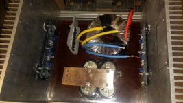
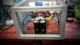
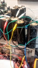
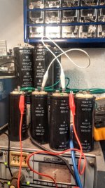
i built F5 not long ago in a standard CRC configuration and was thinking of extending PSU by turning it into CRCLC since i have both inductors (2.2mH EI cored transformers) and caps lying around.
Some people i know suggest however that if i can't hear a slightest hum with my 95db speakers it's better if i simply add another row of caps after the PSU, placing them closer to the amps. This will both reduce ripple slightly and benefit amps with more of that last C in PSU which could sometimes improve dynamics/bass as i am told...
So if anyone tried various PSUs with F5 - is adding 4 inductors to get additional LC worth the effort? Or is it mosly the added C i'll hear the most (if)?
Right now i have dual mono 15000-0.1R-22000 /rail (74000uF per channel). Standard F5 at 26V, 1.4A. Under 200mV of ripple.
Last edited:
I just use any old thing, it works fine.
I think the kits jackinnj shipped came with Vishays, but don;t quote me on that.
I buy mine locally for 5 to a dollar.
BC Components: NTCLE100E3472HB0 -- they are $0.45 in singles from DK.
Hi folks, I'm making slow but steady progress on some F5 monoblocks. I'm using Peter Daniel's boards, and my chassis are pretty tight. The boards will be in the corner, and I'm running leads to the output mosfets. I will solder the gate resistors to the mosfet leg, but I don't see a reasonable way to get the 4.7 thermistors (TH1/2) there. Long leads don't seem like a great idea. If I leave them standing lonesome on the boards, my understanding is that they won't get as hot, so I'll end up running more current through P1 and P2. Is anybody doing this? Can P1 and P2 take it over the long term?
Best,
Paul
Best,
Paul
How to make the best thermal contact? I read about using "goop", but what kind of goopthey , whatever , need to be in contact with heatsink
I thought about that, because one heatsink is pretty close and it would be much easier than mounting them to the mosfets. But wouldn't it mean that the bias would keep moving until the heatsink temp stabilized, which is to say, for quite some time?
Paul
No that's not how it works at all.
The devices will keep warming up and warming the heatsink. At some point (determined by the trimmer settings) the thermistor will begin to pull the bias down but the effect is a small one, and happens with quite a bit of lag (as has been noted).
Since the thermal inertia of the heatsink tends to be extremely large (hopefully) the lag does not cause the bias to trend downward and then up again. The trimmer resistance interacts with the thermistor (note how they are parallel to each other) so the bias stays pretty much constant provided your heatsink is the right size. It's not a problem really.
I've also built without thermistors for a marginal increase in sound quality, but the amp becomes very sensitive to ambient temperatures. If you can keep the external temperature constant you could probably do without. We run from 10 to 40 degrees through the year so it's not possible for us.
Is this a problem?
Took the lid off to check bias and as you can see in the picture R12 has a slight brownish color. None of the other source resistors have this discoloration. It doesn't even feel that warm. Should I change them (source resistors) with a higher wattage?

Took the lid off to check bias and as you can see in the picture R12 has a slight brownish color. None of the other source resistors have this discoloration. It doesn't even feel that warm. Should I change them (source resistors) with a higher wattage?
Took the lid off to check bias and as you can see in the picture R12 has a slight brownish color.
None of the other source resistors have this discoloration. It doesn't even feel that warm.
If it still measures ok and isn't too hot, it's probably just a bad paint job.
If the bias is 1.5A, then 1.5A x 1.5A x 0.47 Ohms = 0.7W
That's more than a factor of 4 derating for a 3W resistor.
Last edited:
If it still measures ok and isn't too hot, it's probably just a bad paint job.
If the bias is 1.5A, then 1.5A x 1.5A x 0.47 Ohms = 0.7W
That's more than a factor of 4 derating for a 3W resistor.
I've tanned that one before....mine is more brown than that, measures fine and is still in there. A while back I was having a hum problem out of no where. Thought it was a roku box, but actually, it was a monitor I was using. During the hum period, (just a slight background hum...this amp is usually dead quiet) I began to smell something "hot" and my resistors were tanned. It got plenty hot, the plastic thing with a little hook on it that connects to multimeter lead melted. I will change them some day, but once I got rid of the monitor amp returned to dead silent and bias is stable. I remember several guys tanning them back in the early F5 days.
Russellc
Last edited:
I build a F5 myself, using the diyaudio PCB's in revision 2.0. I used the recomended resistor values, 2sk170/2sj74 and IRFP240/IRFP9240 transistors. At the begining everything worked like a charm( First firing up/ bias adjustment). But after a couple of days burning in the amp, I run into troubles:
The Bias is adjusted to 1.25A, offset is near zero, but when I power up the amp with cold heatsinks, the power-fets forming a short circuit and the current limiter limits the bias current to about 6A. After a few seconds the bias current goes down to 0.9A and start rising to the desired 1.25A. Final bias is reached after 45min. Power up the amp with warm heatsinks is not an issue. in this case the bias climbs softly to the final 1.25A. The amp sounds wonderful, everything else works perfect.
I`m out of ideas in the moment. Did this have something to do with the termistors? The thermistors have direct contact to the plastic case of IRFP240/IRFP9240. I use thermal conductive paste to archive better thermal contact. It looks like there is a kind of lag in the thermal feadback loop. Did anybody else have this issue? Did anybody have any idea how to fix this? May it help to wire-solder the newer version of the thermistor circuit to the boards in revision 2.0?
Sebastian
- Home
- Amplifiers
- Pass Labs
- F5 power amplifier