Channel AThat means the two channels are working identically.
Or, is there a difference you have not revealed?
I turn one pot one turn then turn other pot one turn
observe Iq and offset proceed one then second pot , for DC output 0.0 Volt
and R11 R12 0.45 Volt.
Channel B
When I move P2 (one turn), DC output rises quickly (approximately 150.0 mV)
and few mV in R11
I move other pot (many turn) increase mV in R11
and DC output 0.0 volt.
I move P2: No increase mV in R11 and DC output rises quickly to 150.00 mV
I move P1 many turn: (no effect)
I move P2 many turn: (no effect)
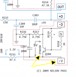
A shot in the dark....I'm not knowledgeable enough to translate between circuits, but those adjustment problems sound very similar to what was happening with a bias boards on my BA3. In that case a defective Q204 was the cause. Maybe one of you gurus can determine if the same thing might be happening here. ")
Attachments
Last edited:
There are differences, but I do not know if it is important,just compare datasheets , and you'll know

because I have little knowledge of electronics.
desolder one side of both output sorce resistors , so mosfets and feedback are out of game
then measure voltages at jfet sources and try to set ,say, 3V across their drain resistors
then report here
You mean:
R11 and R12
R1 and R2
R3 ande R4
desolder one side of both output sorce resistors , so mosfets and feedback are out of game R11 and R12
then measure voltages at jfet sources and try to set ,say, 3V across their drain resistors R3 and R4
then report here
Channel A
I turn one pot one turn then turn other pot one turn
observe Iq and offset proceed one then second pot , for DC output 0.0 Volt
and R11 R12 0.45 Volt.
Channel B
When I move P2 (one turn), DC output rises quickly (approximately 150.0 mV)
and few mV in R11
I move other pot (many turn) increase mV in R11
and DC output 0.0 volt.
I move P2: No increase mV in R11 and DC output rises quickly to 150.00 mV
I move P1 many turn: (no effect)
I move P2 many turn: (no effect)
I unsoldered all passive components and have them checked.
I soldered the components. I replaced Q1 and Q2.
Best result after
P2 many rotations
P1 2 rotations
measurements
dc output 78 mV
R6 + R8 (68 ohm) 0.20 V
R5 + R7 (68 ohm) 1.04 V
R12 0.48 V R11 0.49 V
R4 4.58 V R3 4.86 V
R14 (47 ohm) 52 mV R13 (47 ohm) 29 mV
It hurts my head
I have to succumb my ignorance!!
Last edited:
R12 0.48 V R11 0.49 V
Your almost there, you have it biased up to 1A.
Slowly adjust P1 & P2 for 0.56V across R11 with close to +/-20mV offset at the output, if you can achieve 0mV offset, all the better.
Alternatively, you could leave it as it is and adjust P2 for best offset, it just means you wont achieve the full 25 Watt of class A into 8 ohms.
Last edited:
Your almost there, you have it biased up to 1A.
Slowly adjust P1 & P2 for 0.56V across R11 with close to +/-20mV offset at the output, if you can achieve 0mV offset, all the better.
Alternatively, you could leave it as it is and adjust P2 for best offset, it just means you wont achieve the full 25 Watt of class A into 8 ohms.
my amp does not work so I can not do better.
I'm looking for the fault.
R5 + R7 (68 ohm) 1.04 V
Look for shorts around Q1, drain to source.
I desoldered the R11 e R12
I move P2 in R4 volts rise slowly with the rotations
I move P1 in R3 from 0 to 5.9 volts instantly.
Have you tested P1 functionality out of circuit (off board)?
ARGHHHH....
P1 is faulty!!!
I have desoldered it.
Buy one and replace.
I learned so many things.
thanks a lot
Last edited:

- Home
- Amplifiers
- Pass Labs
- F5 power amplifier