what do you wan't to optain? 200R bleeds the PSU bank exremly fast. burns a lot of Power and drains alot of current the amp could use under operation. it also the transformer and bridge will be under more stress.
Yes, you could put them in series instead.
I don´t care if I burn a nuclear plant as long as it sounds betterwhat do you wan't to optain? 200R bleeds the PSU bank exremly fast. burns a lot of Power and drains alot of current the amp could use under operation. it also the transformer and bridge will be under more stress.
with 1kva x-former a channel and MUR 860 it´s not really an issue what I waist
best
Leif
if you referring to setup posted in #14287 , the you have two choices :
1. pause everything until you learn electronic basics ( how to read schematic and comprehend it to physical layout) , or
2.pause everything until you find someone skilled to finish your project .
sorry , going blind with mains energized equipment is same as going blind on highway
1. pause everything until you learn electronic basics ( how to read schematic and comprehend it to physical layout) , or
2.pause everything until you find someone skilled to finish your project .
sorry , going blind with mains energized equipment is same as going blind on highway
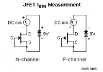
replace the ammeter with a 1k0 resistor.
Measure the voltage drop across the resistor.
Each volt equals a milli-ampere of current.
If the volts drop is too high then swap the 1k0 resistor to a 100r resistor.
each volt equals a 10milli-ampere of current.
The resistor has two advantages.
a.) the prevents a short circuit damaging your jFETs.
b.) you voltmeter is usually far more accurate than your ammeter.
One slight disadvantage is the Vds applied to the jFET varies between devices due to the different volts drop across the resistor.
An adjustable DC power supply allows you to apply the same Vds for all devices.
10m
replace the ammeter with a 1k0 resistor.
Measure the voltage drop across the resistor.
Each volt equals a milli-ampere of current.
If the volts drop is too high then swap the 1k0 resistor to a 100r resistor.
each volt equals a 10milli-ampere of current.
The resistor has two advantages.
a.) the prevents a short circuit damaging your jFETs.
b.) you voltmeter is usually far more accurate than your ammeter.
One slight disadvantage is the Vds applied to the jFET varies between devices due to the different volts drop across the resistor.
An adjustable DC power supply allows you to apply the same Vds for all devices.
10m
1 kohm used and 11,45 V.
7,45 V at R
7.45V across the resistor leaves only 4Vds on the jFET.
Idss is measured with 10Vds
You need to swap in 100r and measure again.
BTW,
that 10m at the end is a typo I missed correcting.
Idss is measured with 10Vds
7.45Vr gives Id=7.45mA when @ 4Vds (11.45-7.45)Measure the voltage drop across the resistor.
Each volt equals a milli-ampere of current.
You need to swap in 100r and measure again.
But reduce the supply voltage to nearer 10V before you connect the jFET. Other wise you risk overheating due to excessive power dissipation in a high Idss device.If the volts drop is too high then swap the 1k0 resistor to a 100r resistor.
BTW,
that 10m at the end is a typo I missed correcting.
Last edited:
the 7.4mA flows when Vds is ~8.3V
That is a different result from earlier.
It also indicates an error in your measuring technique.
The Id has apparently dropped even though the Vds has gone up.
That is not the way jFETs behave !
That is a different result from earlier.
7.45Vr gives Id=7.45mA when @ 4Vds (11.45-7.45)
It also indicates an error in your measuring technique.
The Id has apparently dropped even though the Vds has gone up.
That is not the way jFETs behave !
the 7.4mA flows when Vds is ~8.3V
That is a different result from earlier.
It also indicates an error in your measuring technique.
The Id has apparently dropped even though the Vds has gone up.
That is not the way jFETs behave !
I'll try new measurings with the two voltages, to avoid any error.
Sorry guys, I know I'm becoming annoying but I'm not so dumb as it seems.

No, use 10Vds and measure the Id initially when cold and gradually changing as Tj increases.
This is OK as long as Pdiss << Pmax for the device.
a 400mW device is good for 25% indefinitely
a k170 with 10Vds and Idss @ 7.45mA is only 74.5mW, or ~ 19% of Pmax.
Where it falls down is with devices with an Idss of >>15mA
Tj gets too hot and may damage the device.
None of this tells you the Idss. Idss is when Tj=25°C and Vds =10Vdc.
But good technique does allow comparison.
- Home
- Amplifiers
- Pass Labs
- F5 power amplifier