Front panel design ??
Just finished my standard F5 on a test-heatsink, and connected some old B&W speakers. Wow it sounds terrific!!! Didn't knew that this old speakers could sound so good.
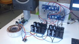
Here are two pics, I use the softstart board and have a total of 352.000 uF/ 35V for the two boards")
Now I'd like to build the F5 into a 3U or 4U Hifi2000 chassis, but I'm looking for a nice frontpanel design.
Does anybody have an example? Maybe even a .dxf or .dwg file format?
I am not that creative, and think drilling and sanding in the nice 10mm frontpanel won't make it any nicer, if I'm doing it myself.
Thanks in advance !
Walter
Just finished my standard F5 on a test-heatsink, and connected some old B&W speakers. Wow it sounds terrific!!! Didn't knew that this old speakers could sound so good.
Here are two pics, I use the softstart board and have a total of 352.000 uF/ 35V for the two boards
Now I'd like to build the F5 into a 3U or 4U Hifi2000 chassis, but I'm looking for a nice frontpanel design.
Does anybody have an example? Maybe even a .dxf or .dwg file format?
I am not that creative, and think drilling and sanding in the nice 10mm frontpanel won't make it any nicer, if I'm doing it myself.
Thanks in advance !
Walter
Attachments
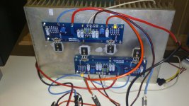
i would move the 4.7K NTC's a little bit. let them tuch the screw for the fet or the center leg.
Just finished my standard F5 on a test-heatsink, and connected some old B&W speakers. Wow it sounds terrific!!! Didn't knew that this old speakers could sound so good.
Here are two pics, I use the softstart board and have a total of 352.000 uF/ 35V for the two boards
Now I'd like to build the F5 into a 3U or 4U Hifi2000 chassis, but I'm looking for a nice frontpanel design.
Does anybody have an example? Maybe even a .dxf or .dwg file format?
I am not that creative, and think drilling and sanding in the nice 10mm frontpanel won't make it any nicer, if I'm doing it myself.
Thanks in advance !
Walter
Servus Walter,
Attach the NTC's with a thermal bonding glue to the MOSFET.
For your configuration (1 pair MOSFETs for each channel) you need only 3U HiFi2000 chassis. I have tested this config with a 3U chassis. The heatsink warm up only to appr. 50 degrees Celsius.
I'm looking also for a nice frontpanel design.
Kindest Regards
Wolfgang
Thanks for your reply Audiosan.
Touching the plastic cover of the MOSFET isn't enough? Even when I glue it with thermal glue in the definitive version?
Touching the center leg is easier and would look nicer I guess...
Wolfgang, that's what I was hoping for, I like the 3U chassis over the 4U.
The heatsink I'm using right now, Fischer SK56 20x30x4 cm, is becoming too hot, with this stereo setup. Aprox. 128 Watts on a 0.3K/W.
So on the back is a little quiet fan right now
Walter
I'd suggest a couple of things also, hopefully without appearing to be a "smart ***".
It appears that you have fuses on the power rails but no dc protection on your O/P - suggest adding one, even if it's a basic unit, as fuses have been known to fail without cause.
If that's a GB bridge (general purpose 35A/200V) feeding your power caps, suggest changing it to an IXYS Shottky bridge or discrete diodes - those GB bridges are convenient and cheap, but this is an easy upgrade for a noticeable improvement in the sound. You have to keep them as cool as possible.
That's a lot of capacitance - 22mF Panasonics? Perhaps an additional small 470uF Nichicon KZ or FG on the pcb (rails) could be beneficial to the sound ....
I can't see any problem about using thermal glue to hold the thermistors to the power Fet's bodies (I hope there's some insulation on the thermistor's leads).
However, AudioSan mentions it's better to glue them directly to the Fet's middle leg - this is interesting and I'd like to know why ...
You're no smart****
I like feedback, it can only make things better...
The fuses are there for initial testing, cause I don't have a variac. They are removed when the amp is build into the chassis.
I will leave out a speaker protection circuit, I even think of cutting out the 10 Ampere limiting circuit...
How are those IXYS Shottky bridge's going to improve the sound? I'm always open for suggestions, but I think all the current will be taken from my indeed large buffercaps, ( yes they are 22mF panasonics from digikey) and the rectifier diodes will not be so important???
I will do some reading about that subject...
Putting a small cap on the PCB is a good suggestion yes, It's a pitty it is not on the PCB already.
Me being a "HAMradio" builder also, I always like to put a lot of decoupling cap's on power rails
it is where the fets are hottest. afterall. this is a thermal protection.
I think you're right, this leg is probably directly connected to the substrate inside... so that is where Í'm gonna glue mij NTC's.
Anybody a suggestion for a nice frontpanel design?
I couldn't sleep at night if I didn't ensure that my precious speakers would get fried if a rail/fet, etc happened - relays, or opto driven power fets, are inaudible in the system. This is an external dc protection package, not part of the amp's design - you can get them anywhere.
The high value, deep etched Panasonics have a 'sound of their own' and the smaller bipass, particularly directly at the power fets is most effective - Nichicons have a "better" sound than the large value Panasonics.
The GB Block bridges use standard diodes and are very handy things - unfortunately, they're also quite noisy things and even tho you have a large value power caps, this "noise" still gets thru and adds "an edge" to the sound - the Shottky diodes don't have this "edge" to the sound, so I call this a "better" sound. Unfortunately, they're not cheap and with 1 bridge per channel it does add up a bit (same if you use discrete diodes) bit the benefits are obvious.
The current limiting components do change the sound slightly - some people prefer it.
The thermistor is there to increase the bias on the O/P Fets as they warm up - not much to do with thermal protection.
I can't clearly see your jfets in the photo but it doesn't seem like you've connected them together for thermal tracking - heatsink goo and a clip (or tie wrap) is essential.
As an old "Ham' you'll be quite comfortable with the idea of making a device to interupt the mains supply to the amp by adding a series globe to reduce the mains voltage, yes? if you haven't access to a variac.
On one of my thick Ali front panels I got the local platers to etch a pseudo dutch pewter surface on it and then added a simple transparent letter decal over that - looks quite neat - the proper grooved lettering is a better finish but a bit pricey with the coloured infil and the surface finish, etc.
Polished wood front panels look okay with the little leds showing through it.
A good amp, well worth a bit of extra effort.
bias
Hi There!
I fired my cviller boards F5c on and got 2.7 volts on R11 and on the speakerterminals dc is running up from zero to 300 mv and still running up more. The mosfets are getting burning hot and there came some smoke from R11 at first. I know the F5c boards are for the turbo version, but I also read that I can use it for normal use. What did I wrong? Is there somebody on the forum who can help me? Than my thankings will be great. Grtz Teake
Hi all,
maybe a stupid question, but... I have got in my box many capacitors I want to use to build a power supply for the F5. but I haven't got 33000uf, so I'm thinking of put in parallele some capacitors to get around 33000uf. Is it a problem to wire in parallele capacitors with different values ? for example I'm thinking of using a 15000uf, with 10000uf and a 6800uf. My transformer is a 700va from my box too.
Thank for your help.
Last edited:
Hi There!
I fired my cviller boards F5c on and got 2.7 volts on R11 and on the speakerterminals dc is running up from zero to 300 mv and still running up more. The mosfets are getting burning hot and there came some smoke from R11 at first. I know the F5c boards are for the turbo version, but I also read that I can use it for normal use. What did I wrong? Is there somebody on the forum who can help me? Than my thankings will be great. Grtz Teake
Did you make sure that the trimmers were set to zero? Sorry if stating the obvious.
I used cvillers pcbs for a standard F5.
Hi all,
maybe a stupid question, but... I have got in my box many capacitors I want to use to build a power supply for the F5. but I haven't got 33000uf, so I'm thinking of put in parallele some capacitors to get around 33000uf. Is it a problem to wire in parallele capacitors with different values ? for example I'm thinking of using a 15000uf, with 10000uf and a 6800uf. My transformer is a 700va from my box too.
Thank for your help.
just go for it
F5
Hi There!
Thanks for the answer. I did not put the pots to zero at first but second time I did. And still the same measurings. For R 1 and R2 I have 10ohm 20 watt caddocks. Could that be the problem also? Is it bether to take a lower wattage? Thanks for the answer, grtz Teake
Hi There!
Thanks for the answer. I did not put the pots to zero at first but second time I did. And still the same measurings. For R 1 and R2 I have 10ohm 20 watt caddocks. Could that be the problem also? Is it bether to take a lower wattage? Thanks for the answer, grtz Teake
- Home
- Amplifiers
- Pass Labs
- F5 power amplifier