Looks like what I had planned is not the right thing to do. I built a Jfet BOZ and was thinking of adding a volume attentuator at the output of jBOZ and connect it to a F5.
This means a volume attentuator at the input of F5, which seems to be not recommended. Means volume attentuator in front of jBOZ?
Thanks.
This means a volume attentuator at the input of F5, which seems to be not recommended. Means volume attentuator in front of jBOZ?
Thanks.
yes the pot should be in front of the jboz, better to buffer the input and output of an attenuator, but if it must be one, it should be before, the jboz should have a high inputz and low outputz, so the input wont be troubled by the pot and the output presents an optimal load to the f5
The F5 already has an adequately high input impedance to be able to be driven by virtually any voltage source. F5 does not need a buffer.
The attenuator pot may need a buffer or two.
It depends on what you use to connect it to the other components and on it's resistance.
If the pot is 50k or 100k, it cannot drive a cable, well, over the whole audio signal range. The higher resistance pots have a higher output impedance and should be buffered to allow them to drive a capacitive load (cable and RF filter).
If the pot is 10k or 5k your sources may have difficulty driving the cable to the attenuator and the attenuator. These two items appears as parallel loads.
The source needs a buffer if it can't drive a low resistance//high capacitance load.
Some fit this buffer at the attenuator. That is the wrong place. The buffer should be driving the cable on the output of any device if the device does nor have adequate current capability.
i screwed up my english above even though i'm native. everything i said was right except for throwing some confusion with these statements conflicting
correctyes the pot should be in front of the jboz
dont know what i was doing there, guess i just had before in my head as in the pot before; because thisbut if it must be one, it should be before,
flows from the first statement. personally i have never made a cable for myself that needed driving, i go for ultra low capacitance cables and not long. although i'm about to, long not capacitivethe jboz should have a high inputz and low outputz, so the input wont be troubled by the pot and the output presents an optimal load to the f5
Last edited:
F-5 power supply confusion...help!!
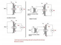
I wired my F-5 up and have not yet installed the thermistors in the primary leads. In the FirstWatt schematic of the power supply, it shows the transformer primaries as "120" "0" "120" "0". Are the center "0" and the center "120" crossing over each other? I thought that was how it was, but another builder has difficulty with that and says the place where they appear to cross should be joined, so the thermistors are together at that end, and his amp does work. Before I screw up my perfect working (except no thermistors) F-5 I want to get this straight. Usually when something appears to pass over but is connected, there is a "dot".....can someone straighten me out on this minor wiring issue?
Russellc
Quote >dont know what i was doing there, guess i just had before in my head as in the pot before; because this
Pot what Pot
Beening smoking it?
flg said:Who's Wine?
What Wine?
Where the H$%&l did I dine???
UUURGH?
something like that, Pinot and flu/medication
the combination was not intentional, but effective


I wired my F-5.....
even if I don't understand your question completely , maybe this will help
Attachments
even if I don't understand your question completely , maybe this will help
Looks like it would, but the pic doesnt blow up big enough for details, maybe its just my crappy computer at work, I'll try again when I get home. Thank you very much for trying clear this up.
Ok, it blows up now, but I dont think it clears up my thick head.
On the FirstWatt schematic for F-5, it appears to have the center two primaries "crossing" over one another, then going to thermistor, or that's how I saw it. I'm dicussing with another who doesnt think they cross there, but are joined, which doesnt make sense to me, but there is a lot I dont understand. I am going to install my thermistors now and was a little confused.
Russellc
Last edited:
Perfect! This is what I thought ! Further conversations reveal I was missunderstanding my friend's comments. He said "nothing in schematic shows crossover" meaning this confuses some, I thought he meant they didnt crossover!
Thankyou! after nap (much needed obviously) I will osmosis and install thermisitors!
Russellc
if you enough practice osmosis - you'll not need any amp

Thanks again, I'll try to cut back with only enough osmosis to install power supply in proper manner, but still need amp.

If amp building attempts dont drive me crazy, something less pleasant will certainly!
Russellc
I am building a pair of F5's, and am tempted to use a pair of tube rectifiers 5r4 military spec types in place of the bridges. Has anyone tried similar variations on the power supply side?
What might be the audable results?
I also have some big old sprague caps 55k 25v would two of these work in place of the four spec'ed electrolytics? And some real nice precision nos .1 ohm 20 watt power resistors. Anyone have some advice about building a ps with these? kinda old school style i guess. How about the start up for the rectifier would this present some turn on challenges with speaker noise?
thanks
anystereo
I am building a pair of F5's, and am tempted to use a pair of tube rectifiers 5r4 military spec types in place of the bridges. Has anyone tried similar variations on the power supply side?
I don't think anybody has tried that. It would certainly be unique.
The added complexity of it would be somewhat daunting, as you would need a filament supply, a novel grounding scheme, and some very interesting transformers. The most interesting thing, to me at least, would be getting the supply adjusted to give the proper voltage, while compensating for the very large forward voltage drop of the 5R4s -- most of the supply voltage will be thrown away in the rectifiers.
Do you have any ideas on how you might implement this?
The other parts you mention would most likely work well. The caps might be dried out...
I have never built anything with a tube rectifier, and don't know know what kind of v losses to expect from these and how to calculate to get 24 v rails. was thinking of a separate transformer to supply the filaments. I guess my motivation comes from my original experience with these rectifiers, which i bought for use in a pair of cary 300b amps, the difference from a a standard 5r4 was remarkable. I regret that i sold the amps, probably out of bordeum but did kept the rectifiers. I suppose the 5r4s complimented the particular nonlinear beauty of the western electrics, and its kinda illogical to think that they would do similar magic for the f5. So, its really just an experiment rooted in a dislike of the diode bridges which are unexamined and so common, - but also feel so terribly artless. I mean they're nasty to solder to, no? the 5r4 were designed for use above 40,000 feet above sea level, Eight Miles high the live version with clarence on guitar well now that'll be the test record. Any thoughts
Actually the diode bridges are examined, and although 'common', do the job very, very well. The amp's designer has said so, as have many others. Also, they require no soldering if you choose to implement them with spades.
As for a wild change in tone/sound by changing the rectifier, you need to understand that the interactions of the rectifiers in a push-pull amp with a V+ V- (dual rail) power supply is significantly different than those in a single-ended, single rail supply. I know and understand the sound of SE amps and their power supplies, and am not trying to belittle your admiration of the rectifier tube --- it's just that it's not apples to apples.
Also, I doubt that they would work as designed at such low voltages.
Last edited:
- Home
- Amplifiers
- Pass Labs
- F5 power amplifier