Well, just don't desolder.
Oh yeah, nothing like a 30 year old paper board with double sided traces that is in bad need for a recap
")
Sorry for OT
Hannes


Bridge rectifier heat
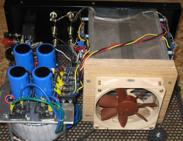
I mounted my bridge rectifiers (35A 200V Vishay diode bridges Mouser 625-GBPC3502-E4) to a 1/8" 5.5" x 5.5" aluminium plate which is mounted horizontally on standoffs directly above my toroid. The plate gets quite hot: 47C. The load is a pair of standard F5 channels biased to 1.3A
Is that much heat from the bridge rectifiers to be expected?
BTW: My toroid is an Antek AN-4220 20VAC, 400VA transformer. Using the Pass power supply design in the F5 Manual, the voltages are +25.1 and -25.1. I recall that earlier posts in this thread raised the question about the DC voltages
from 20VAC transformers.
I have exactly a similar spec toroid in terms of voltage, but at 500VA. The diode bridges are barely warm. My bridges are 50A type and 1000V. AFAIK, the diode bridges should not get so hot in F5. Either the current draw is too much or the bridges are unable to take the current.
I did some more investigation: The bridge rectifier packages are NOT HOT, and none of the components on the PS board are hot. The transformer under aluminium plate is warm, not particularly hot. What is going on?
I disconnected to transformer connections to the rectifiers and powered it on. Everything ran cool, as expected.
The only theory that makes sense is that the bridge rectifier packages are conducting current into the aluminium mounting plate. I mounted them with Thermacote grease and no insulators. If that were the case, I would expect the packages to get hot. Weird!
I did some more investigation: The bridge rectifier packages are NOT HOT, and none of the components on the PS board are hot. The transformer under aluminium plate is warm, not particularly hot. What is going on?
I disconnected to transformer connections to the rectifiers and powered it on. Everything ran cool, as expected.
The only theory that makes sense is that the bridge rectifier packages are conducting current into the aluminium mounting plate. I mounted them with Thermacote grease and no insulators. If that were the case, I would expect the packages to get hot. Weird!
Normally the metal bridge rectifier packages are case insulated, but depends on the specific model you are using. Disconnect the bridge rectifier and check all the four terminals to the body with a dmm for continuity. They should show no continuity.
Could it be that the trasnformer is unable to take the load and is heating up? Are you sure it is 400VA? Also what is the bias level setup up for the F5? is it at stock level or more?
Is the metal plate on top of the transformer connecting to the chassis on the bottom? Looks like you might have a shorting ring on the transformer that would definitely heat up the transformer. Cannot have a conducting ring around the windings.
Well spotted. I think you are right. I have gone back and checked lhquam's earlier posts, which had a larger picture. It seems that there is shorting ring that is formed...with the mounting method.
Before mounting the bridge rectifiers, I checked for any conductivity to the bottom surface of the package. Nothing measurable detected.
The metal plate at the top of the toroid is totally isolated.
I carefully checked how the secondary (and primary) wiring was routed WRT the metal standoffs used to support the aluminium plate. There are no loops where a current loop is formed around one of the standoffs, thus forming an induced current in the standoff.
Next week when I have everything apart for other mods, I will do some more experiments such as insulating the standoffs, testing the temperature when the DC loads are removed, etc.
Is that much heat from the bridge rectifiers to be expected?
Forward voltage of the diodes in a GBPC35 is about 0.75V.
The 1.3A continuous current demand of each output stage rail flows through 2 diodes => Each amp rail generates 1.95W heat in the rectifier bridge.
2 channels => 4 rails => 4 times 1.95W => 7.8W rectifier bridge dissipation.
47C plate temperature at 22C ambient is 25C temperature rise.
25C divided by 7.8W makes 3.2C/W thermal resistance for the 5.5"x5.5" plate.
3.2C/W reference heatsink =>www.farnell.com/datasheets/310885.pdf
Yeah, baby, Class A is so shagadelic !
Yup. Those calculations make sense. In the future I will do one of the following:
. Use Schottky diodes for lower voltage drop.
. Use a heatsink for the rectifiers
. Mount bridge rectifiers on the chassis where there is more surface area to provide a lower thermal resistance.
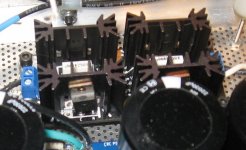
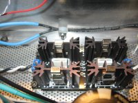
Heatsinks for rectifiers
As Christian (Cviller) suggested when I was building my F5. Use high quality heatsinks and CLIPS to secure Diodes to the HS. Very clean looking with snubbers too!
Ron
As Christian (Cviller) suggested when I was building my F5. Use high quality heatsinks and CLIPS to secure Diodes to the HS. Very clean looking with snubbers too!
Ron
Attachments
Last edited:
I'm sorry, but that is only true if the current through the diode bridges, and by extension the transformer secondaries, was sinusoidal. Unfortunately in a rectified PSU with smoothing capacitors it is anything but, because the diodes are only able to conduct for the small time window near the peak of the AC voltage cycle, where the secondary voltage is higher than the one across the smoothing capacitor bank plus the total diode drop.Forward voltage of the diodes in a GBPC35 is about 0.75V.
The 1.3A continuous current demand of each output stage rail flows through 2 diodes => Each amp rail generates 1.95W heat in the rectifier bridge.
2 channels => 4 rails => 4 times 1.95W => 7.8W rectifier bridge dissipation
In order to figure out what the real RMS current loads on the rectifier bridges and the transformer secondaries is, you need to know a bit about the schematic and the components used. In particular the smoothing capacitance seen by the rectifiers, the total reflected loss resistance of the transformer, the voltages, mains frequency, and load current is needed. Then a graphical solution exists, which yields RMS current load of transformer and rectifiers as a fraction of the load current.
In modern, passive SS PSU schematics the correction factor is usually somewhere between 2.5 and 4.5, though values outside this interval is possible in extreme cases. Outer limits are 1.584 as low and about 6 as the high factor. This is the cause for the stories about overheating transformers you hear from time to time, as many DIYers tend to forget about correcting the transformer VA load when buying components.
Source: Radiotron Designers Handbook, 4th Edition, 1953: Section 30.2.III, page 1174: "To determine peak and average diode currents".
Figure 30.8 is what you are looking for.
- Frank.
I'm sorry too, it was not meant to be an exact answer, merely an answer to the question asked.
All here will be aware that :
-rectifier diodes conduct for short time frames only
-current levels are consequently much higher-
-average diode forward voltage level will be much higher
-ergo, rectifier bridge dissipation will be higher.
If you can answer Ihquam's question within the ~60 seconds it took me, be my guest.
If not, then you're a smart *** who jumps at every opportunity to show off vast EE knowledge.
YMMV.
- Home
- Amplifiers
- Pass Labs
- F5 power amplifier