Hi,
Nothing new here, but I am very happy I started to tweak the amp, just to get hands on on how things go.
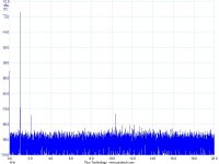
The first picture is the FFT of the signal of my generator. I think not the best (anyone can recommend any good software or file to use? )
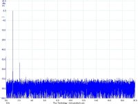
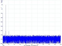
On the left channel I measure THD 0.02 % at 4 W and I have more than double on the right one. So I started playing with the right channel. I attached a 3 ohm resistor on one side and the distortion went up, so I moved to the other side and I brought back the distortion to 0.02 % adding two 0.47 ohm in parallel. I was really easy, and it did not move the bias and the DC offset of the amp.
Is there a lower limit for the source resistor ?
The pictures are before and after.
Fun !
D.
Nothing new here, but I am very happy I started to tweak the amp, just to get hands on on how things go.
The first picture is the FFT of the signal of my generator. I think not the best (anyone can recommend any good software or file to use? )
On the left channel I measure THD 0.02 % at 4 W and I have more than double on the right one. So I started playing with the right channel. I attached a 3 ohm resistor on one side and the distortion went up, so I moved to the other side and I brought back the distortion to 0.02 % adding two 0.47 ohm in parallel. I was really easy, and it did not move the bias and the DC offset of the amp.
Is there a lower limit for the source resistor ?
The pictures are before and after.
Fun !
D.
Attachments
> What is NOT perfectly clear to me (if this is correct) is why it does not make sense to twick the first stage only and not the second one.
Because the 2SK1530 / 2SJ201 are perfectly complementary, and the 2SK170/ 2SJ74 are not.
So the latter need some help from the 5.1R degeneration resistor.
All explained before.
Patrick
Patrick, my question was different: I would like to put the 5.1 ohm resistor on the first stage even with IR mosfet. From my understanding it still makes sense.
Thanks,
Davide
I have not measured the IRFP P-devices. No no idea whether they are truely complementary. I avoid using them because of the frequency problem with the P-Channel device as published by Nelson.
If they are not, then the 5R at the JFETs only makes the front end symmetrical. You still have to solve the real end asymmetry somehow.
Patrick
PS take AndrewT's advice and use a distortion magnifier for your distortion tuning.
If they are not, then the 5R at the JFETs only makes the front end symmetrical. You still have to solve the real end asymmetry somehow.
Patrick
PS take AndrewT's advice and use a distortion magnifier for your distortion tuning.
I have not measured the IRFP P-devices. No no idea whether they are truely complementary. I avoid using them because of the frequency problem with the P-Channel device as published by Nelson.
If they are not, then the 5R at the JFETs only makes the front end symmetrical. You still have to solve the real end asymmetry somehow.
Patrick
PS take AndrewT's advice and use a distortion magnifier for your distortion tuning.
I am using Vishay Mosfet, that although are not fully complementary like Toshiba should not have the problem reported by NP.
I'm looking into the distortion magnifier. I'll order the article. I saw there are even kits available. But I think I would better get a decent generator first.
D.
Hi woody, I still have some psu boards available (cviller order site), but you can also solder a nice psu on perf board. The psu for F5 is really simple, but you should look around for the capacitors, as they are often hard find for a good price. Do you prefer snap-ins or screw mount?
There is a guy in the states selling antek transformers on ebay and possible also here - if you haven't already found the one you need.
thanx 6L6 and cviller , what parts are needed for your psu boards cviller ?
no preference as to snapin or screw as this is only my second build and yes on the antecs . i used a pair of them in my PD gainclone . very nice quality .
does digikey have the required caps ?
thanx
thanx 6L6 and cviller , what parts are needed for your psu boards cviller ?
no preference as to snapin or screw as this is only my second build and yes on the antecs . i used a pair of them in my PD gainclone . very nice quality .
does digikey have the required caps ?
thanx
I have the required components for the psu listed here: http://www.diyaudio.com/forums/group-buys/134554-gb-f5-pcb-11.html#post1683288
And yes, you can definitely get the caps at digikey.
I am using Vishay Mosfet, that although are not fully complementary like Toshiba should not have the problem reported by NP...
Vishay Brand MOSFETs are the IR MOSFETs. IR sold that portion of their bisiness to Vishay 4 years ago.

To DC block or not, that is the question
I finally finished my F5 and decided that it was trustworthy enough to install in my stereo system (Squeezebox, McIntosh C504 preamp (circa approx 1986) and B&W CDM1 speakers).
I found that the offset voltage of each channel went to about 60 mv (from near zero) when connected to the preamp. Measuring the dc level of the preamps verified that the preamp channels have about 10 mv dc output. Apparently the 10uf non-polar DC blocking caps in the preamp are leaking a little.
My question is whether to simply adjust the F5 to accomodate that offset at the inputs, install blocking caps in the F5, or replace the blocking caps of the preamp.
1st things first - get your preamp sorted - [B].... replace the blocking caps of the preamp[/B] - good quality film ones will also give a big improvement in sound quality - film caps do usually take awhile to "settle down" to their final sound - also have a look at replacing all the other electros, as 25 years old.
1mW is ~-47dB ref maximum power of the F5 (50W into 4r0).60mV...that's about 1 milliWatt into your 4R speaker
If one had noise at a level of -47dB one would be in tears after spending all that money.
Output offset is a "noise", if anyone will allow DC to be a noise. It certainly should not be there and certainly not considered acceptable.
If high efficiency speakers are being used with the F5 then it's even more important to minimise the output offset.
I connected up my F5 to the mains this morning without the bulb tester and after several seconds the fuse blew. The right channel was disconnected. The left channel did not blow the fuse but adjusting P1 does not do anything; P2 adjusts the voltage across R12 and alters the dc offset. Nothing went pop on the pcb's and there was no smoke. Have I cooked Q3 on the left channel? Any advice as to what to check would be much appreciated. TIA
Unplug.
Discharge all the capacitors with a power resistor.
The electrolytics will appear to recharge due to energy storage in the di-electric.
Discharge them at least twice and measure voltages before you start the next stage.
Measure the resistance of the Output mosFETs.
D to S and S to D.
Discharge all the capacitors with a power resistor.
The electrolytics will appear to recharge due to energy storage in the di-electric.
Discharge them at least twice and measure voltages before you start the next stage.
Measure the resistance of the Output mosFETs.
D to S and S to D.
Last edited:
- Home
- Amplifiers
- Pass Labs
- F5 power amplifier