Re: Re: PROFET Question
So 6.8 ohms output impedance is far away than a R2R design thus a lot of power "lost" for a common source output stage...
Also I could not get THD (1KHz) lower than 0.6% at 16Vac with 23Vdc power supply (at higher level it clipped but with a gradual rounded shape instead of flat) ... THD at low level was about 0.2%....is it consistent with Profet amp spec?
Unless using a hig hvoltage supply, I guess such a power amp design (Profet or F5) is not for Laterals... I have a few that I wanted to use...
Nelson Pass said:
That appears to be consistent with "Chuck" Hansen's review of the
Profet in AX magazine, in which he measured a 6.8 ohm output
impedance. That doesn't mean that the amp sounds bad, but it
tends to limit its application.
So 6.8 ohms output impedance is far away than a R2R design thus a lot of power "lost" for a common source output stage...
Also I could not get THD (1KHz) lower than 0.6% at 16Vac with 23Vdc power supply (at higher level it clipped but with a gradual rounded shape instead of flat) ... THD at low level was about 0.2%....is it consistent with Profet amp spec?
Unless using a hig hvoltage supply, I guess such a power amp design (Profet or F5) is not for Laterals...
I have a few that I wanted to use...Re: Re: Re: PROFET Question
1. How many laterals do you have? Parallel them. You will not need source resistors even if you parallel them, laterals have positive tempco already at very low currents (if I recall correctly, these have zero tempco at around 100mA.)
2. Q9 and Q10 are not really needed at this low supply voltage. Btw, with the biasing resis-tor values shown in your scematic, they allow for only 2.5-3V over the JFets. This is low for high input signal levels.
3. I am puzzled about the values for P1 and P2. The laterals need around 1.5 - 2V G-S for 0.6A bias. That means only 2mA through the JFets??
I think that your main problem is the low transconductance of the laterals and the low Gate Source voltage needed to "open" them. Both result in a much lower OLG than the F5.
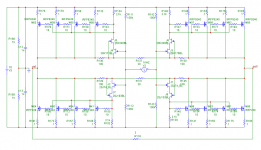
I suggest you a workaround according to this schematic:
Current sources with parallel resistors instead drain resistors P1/P2. This allows to increase OLG despite low voltage drop.
I have used your cascode transistors for that
Use the F5 feedback arrangement, it allows for lower degeneration despite same source R.
The resistor values are starting values. No sim values! You have to tweak them, maybe massively.
Success, Tino
Don't give up so soon.fab said:Unless using a hig hvoltage supply, I guess such a power amp design (Profet or F5) is not for Laterals...
1. How many laterals do you have? Parallel them. You will not need source resistors even if you parallel them, laterals have positive tempco already at very low currents (if I recall correctly, these have zero tempco at around 100mA.)
2. Q9 and Q10 are not really needed at this low supply voltage. Btw, with the biasing resis-tor values shown in your scematic, they allow for only 2.5-3V over the JFets. This is low for high input signal levels.
3. I am puzzled about the values for P1 and P2. The laterals need around 1.5 - 2V G-S for 0.6A bias. That means only 2mA through the JFets??
I think that your main problem is the low transconductance of the laterals and the low Gate Source voltage needed to "open" them. Both result in a much lower OLG than the F5.
I suggest you a workaround according to this schematic:
Current sources with parallel resistors instead drain resistors P1/P2. This allows to increase OLG despite low voltage drop.
I have used your cascode transistors for that
Use the F5 feedback arrangement, it allows for lower degeneration despite same source R.
The resistor values are starting values. No sim values! You have to tweak them, maybe massively.
Success, Tino
Attachments
I have some questions before starting the building :
1) does F5 need a preamp?
2) may I decrease R11 and R12 slightly to 0,5 ohm?
3) If I use Fostex drivers as FE206 , are applyable the same tecniques described in " current source amplification " when my needs comes down to equalization? For Both F5 and F3 ?
edit: 4) Are ok 2sj109 here ?
thanks
1) does F5 need a preamp?
2) may I decrease R11 and R12 slightly to 0,5 ohm?
3) If I use Fostex drivers as FE206 , are applyable the same tecniques described in " current source amplification " when my needs comes down to equalization? For Both F5 and F3 ?
edit: 4) Are ok 2sj109 here ?
thanks
1) does F5 need a preamp?
No, it has enough gain depending on the sources
2) may I decrease R11 and R12 slightly to 0,5 ohm?
You mean increase? Yes, no problem.
3) If I use Fostex drivers as FE206 , are applyable the same tecniques described in " current source amplification " when my needs comes down to equalization? For Both F5 and F3 ?
The F3 and F5 are not current sources - the equalization
technique for current source amps will not work.
4) Are ok 2sj109 here ?
Yes.

thermistor
I'm going to try some Cantherm thermistors from digiKey, part # 317-1360-nd. My plan is to drill a small hole in the heatsink next to the mosfet and stick the head of the thermistor in it, insulate the leads and run them back to whatever pcb I decide to make for this amp.
George
I'm going to try some Cantherm thermistors from digiKey, part # 317-1360-nd. My plan is to drill a small hole in the heatsink next to the mosfet and stick the head of the thermistor in it, insulate the leads and run them back to whatever pcb I decide to make for this amp.
George
Will this one do:
http://www2.schukat.com/schukat/sch...View?OpenDocument&art=K164NK004,7-10&wg=C4010
??
http://www2.schukat.com/schukat/sch...View?OpenDocument&art=K164NK004,7-10&wg=C4010
??
Remember that the thermistors are mostly a convenience. You
can build a fine F5 without them, so there's not too much reason
to get excited about the specific part and such. Having said that,
my preference is to just glue them to the top of the plastic
case on the transistor.
can build a fine F5 without them, so there's not too much reason
to get excited about the specific part and such. Having said that,
my preference is to just glue them to the top of the plastic
case on the transistor.
Mega Power Hyper Balanced F5 Amp
I have not had a too many chances to work on the balanced design (I've been busy with the birth my first child) but I can't sit still when it comes to improve my design.
I have also upgraded my computer to an iMac and had been re-organising my collections of design and application notes, and while I was browsing (for you windows users OSX has a 'cover flow' view of its files, which is just like cover flow for iTunes except it lets you browse through the front pages of all of your documents, pictures and pdf's, its a great way to look through your old articles) I re-found my Erno Borbely articles called "JFETS: The New Frontier". These articles talked about how to make the most of the JFETs and one of the examples was to cascode the 2SK170 with a 2SK246.
When I previously tried cascoding I cascoded the JFETs with MOSFETs but all the extra components with no appreciable performance gains put me off but the simplicity of cascoding a JFET with a high pinch off voltage JFET is very attractive so I tried it.
What I found was it enabled lower distortion while running lower bias in the output transistors (.8A vs 1.2A) and with the lower dissipation per device it would let me run more devices in parallel to get lower output impedance so the circuit can drive lower impedance load at low distortion.
This circuit can drive 120Vp-p or 900W into 2R Load at about 0.12% distortion.
Bandwidth is still wide at 230kHz and output impedance is about 0.03R
Of course the compromise is, the unit will still be drawing and dissipating 460W of power continuously so there will need to be huge heatsinks and huge power supplies.
Attachments
Re:who cares for Mega Power Hyper Balanced F5 Amp,when


TimS said:............I've been busy with the birth my first child)...............
Re: Mega Power Hyper Balanced F5 Amp
That's not a compromise
cute idea
Magura
TimS said:
Of course the compromise is, the unit will still be drawing and dissipating 460W of power continuously so there will need to be huge heatsinks and huge power supplies.
That's not a compromise
cute idea
Magura
Re: Mega Power Hyper Balanced F5 Amp
My first born is now a jet-jockey.
I can appreciate the comment. When he arrived on the scene I would do the 2:00 a.m. feeding -- usually with a Budweiser for me and milk for him, but sometimes a wee bit of the hops would calm him down. In New York we had the "Joe Franklin" show on TV in those wee hours of the morning, probably interviewing Rudy Vallee or some protege of Enrico Caruso. I would trundle off on the 6:30 a.m. train into NYC like someone who had missed that particular episode of the 12-step program.
Just remember to remind your wife that child-birth is more painful for the husband, after all she had an epidural.
TimS said:(I've been busy with the birth my first child)
My first born is now a jet-jockey.
I can appreciate the comment. When he arrived on the scene I would do the 2:00 a.m. feeding -- usually with a Budweiser for me and milk for him, but sometimes a wee bit of the hops would calm him down. In New York we had the "Joe Franklin" show on TV in those wee hours of the morning, probably interviewing Rudy Vallee or some protege of Enrico Caruso. I would trundle off on the 6:30 a.m. train into NYC like someone who had missed that particular episode of the 12-step program.
Just remember to remind your wife that child-birth is more painful for the husband, after all she had an epidural.
Profet like amp
Thanks Nelson for the cheer up but I was not referring about the sound but only efficiency for a class A amp with only about +/- 20 to 24 Vdc power supply. Also, since the overall gain depends largely on the load impedance I am worried for gain variation since the speaker impedance varies with frequency...
Again I am talking about Laterals use here.
For the cascode at input it is more for AC behavior (reduce input capacitance and memory effect) than DC power concern of jfet. What is hte problem with high input signal?
Exactly what I wanted to point out. That is why it can be difficult to "tweak" it to be similar to F5...
The latetal version may probably make an interesting headphone amp...
Nelson Pass said:Offhand, the numbers look consistent with Hansen's measurements
of the Profet.
Perhaps you are being harsh in judging your amplifier. Those
numbers do not necessarily mean that it sounds bad, nor does it
mean that you are done tweaking this until it sounds better yet.
Thanks Nelson for the cheer up but I was not referring about the sound but only efficiency for a class A amp with only about +/- 20 to 24 Vdc power supply. Also, since the overall gain depends largely on the load impedance I am worried for gain variation since the speaker impedance varies with frequency...
Again I am talking about Laterals use here.
Thanks Tino.zinsula said:
...
2. Q9 and Q10 are not really needed at this low supply voltage. Btw, with the biasing resis-tor values shown in your scematic, they allow for only 2.5-3V over the JFets. This is low for high input signal levels.
For the cascode at input it is more for AC behavior (reduce input capacitance and memory effect) than DC power concern of jfet. What is hte problem with high input signal?
thanks I will give it some atttention if it can compensate for the loss of gain caused by tghe Lateral use. There is however a mistake regarding the part number of the N and P mosfets...zinsula said:
I suggest you a workaround according to this schematic:
...
The resistor values are starting values. No sim values! You have to tweak them, maybe massively.
zinsula said:
I think that your main problem is the low transconductance of the laterals and the low Gate Source voltage needed to "open" them. Both result in a much lower OLG than the F5.
Exactly what I wanted to point out. That is why it can be difficult to "tweak" it to be similar to F5...
The latetal version may probably make an interesting headphone amp...
- Home
- Amplifiers
- Pass Labs
- F5 power amplifier