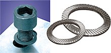
no, that is another "shake proof" type.What you need is called a toothed washer
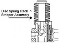
It also says that the cupped disc washer may make the bolt tension fail without a locking device
Anyway, fore the kind of relatively low tension pressure we need, the normal cupped disc washer may not work at all
Lots of variables that needs to be calculated
Tho, I have seen some very light and thin cupped disc washers, but they are made fore no or very low tension, like to take care of "play" where hair split copper pins are the only security device
Or used in a moving construction where a minimum of play is needed
The shake proof toothed washer will ensure that the screw/bolt stays in place, even with the relatively light tension we need...thats why
It also says that the cupped disc washer may make the bolt tension fail without a locking device
Anyway, fore the kind of relatively low tension pressure we need, the normal cupped disc washer may not work at all
Lots of variables that needs to be calculated
The shake proof toothed washer will ensure that the screw/bolt stays in place, even with the relatively light tension we need...thats why
That's been my experience.


Would simply lapping the back of the FET to the matching portion of heatsink work here? Neither needs to be perfect, but only to match each other.
No. Not a good plan.
The problem is not some sort of curvature (not that you can match that if it is there), but surface roughness or irregularity. Both surfaces need to be flat. The Mosfet bottom is flat, the mica is flat, now the heatsink needs to also be flat.
Simple enough.
Oh, from the factory the extrusion's surface may or may not be flat enough... so if you try to flatten the surface, be sure to make flat long strokes backed by a flat stiff object. You do not want to make a smooth but concave area!
_-_-
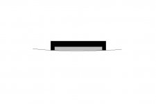
Well, the real bad thing about non plane heatsinks are that just the slightest whatsoever small non linearity results in the device standing on its edges only
Its not uncommon that heatsinks are curved like in drawing
Basicly happens because of the fins
And you can try and sand it from now until end of days, it wont help
Apart from machining, maybe the best one can do is to just carefully sand away the plastic edges on device, as a smaller device means smaller problem
But first determine how much of a problem there actually is
Place something small and plane on the heatsink
With a small penlight you will see how much it really is
Attachments
Tinitus, we have a minor disagreement on your point...
If one uses a dead flat backing and successively finer grit one will get a flat area as a result. Referring to your drawing, you show the black object making contact on just the edges, this is precisely what will happen if you use a dead flat backing while abrading the surface, the edge will cut first, then finally you will get contact to the center...
Using "machinists blue" you can determine your contact area. A permanent marking pen is a good enough second best for this test. The areas not being touched by the abrasive or flatedge will remain colored.
Reducing the size of the device is not a good idea in general.
I do agree that if you take a known flat (of appropriate dimension) and lay it on the surface, a bright light from the other side will reveal many issues.
It will not reveal a surface that is flat overall but that has a groove ^^^^^ pattern from something like a mill or flycutter. That too will create a reduction in contact surface area.
_-_-bear
_-_-bear
Imo, don't use plastic anything to hold things like these output devices.
Plastic is not dimensionally stable. It may work fine for a while, but not for a very long while. Imo.
While they do sell an insulating washer for isolating screws from the device, I try very hard to not use them for power devices that run hot (like these). this makes the clamp solution attractive as an alternative...
imo, of course. Ymmv - but use high test whenever possible! ;D
_-_-
Reducing the size of the device is not a good idea in general.
I never suggested that
Its not about reducing size
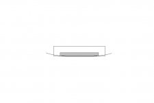
Its about doing what "resembles" that of a smaller sized device, less play
Its about "forming" the back of device, by sanding the edges only
This is similar to reduced width resulting in less play, thus better heat transfer
Its close to what was previously suggested with sanding the back of device
And mostly what would happen doing it that way
I have tried sanding a black heatsink, and Im not doing it again
My new heatsink is raw alu finish, and perfectly plane
My other black ones are not
Attachments
I want to share some more impressions for the f5.
As I said I use large skins, so after many hours the temperature stays to about 40oC, so after reading I started playing with the bias...
0.60v >>> 40oC >>> 65oC (mosfet)
0.71v >>> 43oC >>> 80oC (mosfet after 30min)
The weird is that the two of this positions gives a different sound!
The big difference was in the bass area and the mids (I beleive highs were the same)
So my results,
in 0.60v I had a huge, great bass (the midbass was thin), the mids were little behind and the highs were very good
in 0.71v the bass gone away but the midbass became huge, the mids left the veil and became huge (I liked them, but where is the bass), the highs also had a little better volume.
now 0.65v and here are all, perfect balance for all.
Anyone with the same experience?
I have some good news!
Micro Grit+using kapton insulators + arctic Mx2 (just a very thin film to help no visible scratches) + get rid of the clamps
0.60v >>> 41oC (heatsink)>>> 46oC to 49oC (mosfets)
The output offset is more stable. And the sound is very balanced now!
Next thing, is to check higher bias, but I am afraid the 300va trafo isn't enough! (becomes very hot)
Thanks for your help
Last edited:
Tinitus,
I see what you are saying but I don't think it really works.
If there is sufficient curvature to keep the center part from transferring heat as in the first drawing, and you modify it to look like the second drawing I think that you will only have edge contact, and the center area will be a very hot spot.
Better to use a silpad since they are designed to suck up some difference?
I've had not difficulty with black or any other color anodized heatsinks when it comes to machining or "sanding"... if ur new heatsinks are un anodized then the top surface will be soft (but you said it is flat anyhow). Anodize is hard. What they call "hard anodize" is, well, harder!
Prooptiki - what is "micro grit"??
_-_-bear
I see what you are saying but I don't think it really works.
I think that you will only have edge contact, and the center area will be a very hot spot.
It works
I didnt say it would be perfect
But still better than doing nothing
Play will be less, and pads/grease more effective
But there is a better and more professional way
And it doesnt need advanced tools
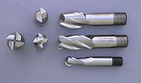
You need a stationary drill machine, and an endmillling cutter
With the endmilling cutter you should be able "spot mill" around where the output device is supposed to be
I havent tried it yet
Attachments

how many channels are being powered by this transformer?Next thing, is to check higher bias, but I am afraid the 300va trafo isn't enough! (becomes very hot)
What is the transformer?
What is the continuous current draw from the PSU, i.e. output bias plus amplifier quiescent current?
and how do you propose to machine/grind/sand the spotface to make it flat enough to conduct heat from the device, with minimal Rth s-a?With the endmilling cutter you should be able "spot mill" around where the output device is supposed to be
I havent tried it yet
- Home
- Amplifiers
- Pass Labs
- F5 power amplifier