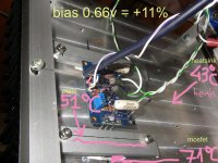
As I said I use large skins, so after many hours the temperature stays to about 40oC, so after reading I started playing with the bias...
0.60v >>> 40oC >>> 65oC (mosfet)
0.71v >>> 43oC >>> 80oC (mosfet after 30min)
Btw, there is a parallel thread just for discussion of listening impressions WRT circuit changes and implementations...
but wondering what your temperature measurements are showing?
is the first number the starting temperature?
Or is that the temperature of the heatsink??
IF the mosfet is 80 C and the heatsink is 43 C then you have a problem with the coupling between the mosfet and the heatsink.
_-_-bear
The (0.60v) 40oc is the temperature of the heatsink, but excactly behind the mosfets the upper half part of the heatsink, the bottom part is colder!
at 0.71v the heatsink becomes hotter in the bottom too 43-44oC, I specified also that I test it only for 30minutes, maybe after some more hour would become hotter. But I beleive 80oC to the mosfet is not that bad, is it?
proop,
you're temperature measurements do not make sense.
You have increased the bias current by 0.71/0.60 = +18.3%.
Something is seriously not right. Either the data or the build.
I am going to check it again, after some time, but now I use 0.655v +9% bias so what temperature should I expect?
That depends on your heatsink characteristics and having the the mosfets correctly insulated and correctly attached as well as your voltage and bias. Lots of factors. Just come back with a description and measurements. Its kinda hot ") But they are not going to die while you wait to get measurements. They might last years like that.
But they are not going to die while you wait to get measurements. They might last years like that.
Uriah
But they are not going to die while you wait to get measurements. They might last years like that.Uriah
Ok, Mr. Pass, are you saying that the "sound" of the amp changes with bias setting?
Is this a measurable change in frequency response?? Or?
_-_-bear
Absolutely the sound of an/the amp changes with bias. If it didn't why bias high?
Absolutely the sound of an/the amp changes with bias. If it didn't why bias high?
I thought high bias was to lower distortion.
Ok, Mr. Pass, are you saying that the "sound" of the amp changes with bias setting?
Is this a measurable change in frequency response??
The amount and spectral content of distortion changes
measurably, and there is subtle alteration of gain, damping,
and frequency response.
For whatever reason, though, it is not an uncommon
subjective observation.
Example: The Aleph 5 has proportionally lower bias than
other members of the Aleph family, but was noted for its
punchy bass.
I thought high bias was to lower distortion.
Sure, and if you lower the distortion I'm guessing the sound would change, presumably for the better.
I just measured Rick's F5 implementation using a non contact IR thermometer.
It has seemingly proven to be accurate when used elsewhere.
I found very little temperature differential between the case of the Mosfet and the local area around the mosfet on the heatsink. I checked the heatsink at a distance of a few inches or so away to avoid the potential for a wide pickup pattern from the IR thermometer, no change in my observations.
After about an hour of operation the temp (iirc) of the heatsink was ~100F (I can't relate to C, sorry). The temp differential between the mosfets and the heatsink was about 5 deg F. Kapton insulators were being used.
He is using very large heatsinks, and it was a cool room, but the differential between the heatsinks and the mosfets was not great.
I also checked my large Symphony No.1 Amp which is high bias AB (runs more quiescent current than the F5 actually...) and those mosfets were similarly only about 10-15deg F differential to the heatsink... and a few degrees hotter, which is expected due to the current and the size of the heatsink & its efficiency.
prooptiki, that high reading with the lower reading on the heatsink seems to indicate that you do not have a low thermal resistance path between the heatsink and the mosfet - nor to the top clamp!!
_-_-bear
Last edited:
The amount and spectral content of distortion changes
measurably, and there is subtle alteration of gain, damping,
and frequency response.
For whatever reason, though, it is not an uncommon
subjective observation.
Example: The Aleph 5 has proportionally lower bias than
other members of the Aleph family, but was noted for its
punchy bass.
Wouldst thou posteth graphicus examplus?? (F5 only...)
_-_-bear
After about an hour of operation the temp (iirc) of the heatsink was ~100F
(I can't relate to C, sorry).
The temp differential between the mosfets and the heatsink was about 5 deg F. Kapton insulators were being used.
_-_-bear
metric-conversion.org
But thats what I thought
Low case/heatsink difference due to general low heatsink temperature
100F equals 37.777 celcius
Could it also indicate low bias ?
I just measured Rick's F5 implementation using a non contact IR thermometer.
It has seemingly proven to be accurate when used elsewhere.
I found very little temperature differential between the case of the Mosfet and the local area around the mosfet on the heatsink. I checked the heatsink at a distance of a few inches or so away to avoid the potential for a wide pickup pattern from the IR thermometer, no change in my observations.
After about an hour of operation the temp (iirc) of the heatsink was ~100F (I can't relate to C, sorry). The temp differential between the mosfets and the heatsink was about 5 deg F. Kapton insulators were being used.
He is using very large heatsinks, and it was a cool room, but the differential between the heatsinks and the mosfets was not great.
I also checked my large Symphony No.1 Amp which is high bias AB (runs more quiescent current than the F5 actually...) and those mosfets were similarly only about 10-15deg F differential to the heatsink... and a few degrees hotter, which is expected due to the current and the size of the heatsink & its efficiency.
prooptiki, that high reading with the lower reading on the heatsink seems to indicate that you do not have a low thermal resistance path between the heatsink and the mosfet - nor to the top clamp!!
_-_-bear
maybe the clamp is the problem!
I use akasa Thermal Adhesive Tape 0.9 W/m.°C with a hole in the middle of mosfet, filled with Silver based thermal compound 9.24 W/m.°C
is the Kapton insulator 0.45W/m.K better?
maybe the clamp is the problem!
I have looked at the last picture , showing your clamping
It may have some good effect
But if not tightened 100% correct, and perfectly equal at both ends, its a potential risk that it can "tip" the device
And that it bends may not make it any better
It takes a lot of mechanical experience to do those tricks properly
The potential risk of it failing is huge
Place a brick between clamping and device
And pressure it down with a metric machine screw through the clamping
Im sure that will do the trick
One thing that could make it worth it is to put the pressure in the middle of the device
In think it a small but general flaw that the screw hole on the device is placed at one end
And why its sensible to at least use big thick shims
On the other hand
The device casing is constructed in way so that the hole is where pressure is supposed to be placed, I suppose
metric-conversion.org
But thats what I thought
Low case/heatsink difference due to general low heatsink temperature
100F equals 37.777 celcius
Could it also indicate low bias ?
Afaik the bias is correctly set. It is not cold - it is a big heatsink, it gets rid of heat. A good thermal connection makes the mosfet conduct heat to the heatsink.
As I mentioned, I tested my own amp, and it has heatsinks warm to the touch, but not more than that, with little differential temperature between the metal Hitachi's and the heatsink itself. (Edit: by warm I mean not so hot that you can not touch it, but it's what someone with sensitive fingers would call "hot" - but things have to be >160F before it is actually "hot"...)
sounds to me like prooptiki is not getting proper thermal conduction to the heatsink.
Btw, the heatsink surface needs to be flat and smooth as well...
otherwise the interface looks like this ascii drawing: (use ur imagination)
|mosfet|
^^^^^^^^^^^^^^^^^^^^^^ <---heatsink surface
this gives much much less surface to contact.
_-_-bear
EDIT: PS tinitus, my amp had been running more than 24hrs... so assuming that the thermal circuit was low resistance, then the Hitachi's and the heatsink should have both raised in temperature to some point of thermal stasis - IF the interface between the mosfets (Hitachi's in this case) was not low resistance then the temperature of the case would have risen to a higher final temperature and faster than the heatsink. We are not seeing this in my amp nor in Rick's F5 either.
Last edited:
I have that thermal adhesive tape from Akasa too, but I don't use it for the F5 - it is got too much thermal resistance. actually, it can only be safely used for one or two watts of heat dissipation.
I would change it for mica - I use a thinned mica sheet and some thermal compund (generic) and I have a 10 degree difference between MOSFET case and the sink, and a max delta of 5 degrees across the sink surface.
I would change it for mica - I use a thinned mica sheet and some thermal compund (generic) and I have a 10 degree difference between MOSFET case and the sink, and a max delta of 5 degrees across the sink surface.
- Home
- Amplifiers
- Pass Labs
- F5 power amplifier