Re: Re: looks like a regulated PS
When I design PS boards, I try to give them wider appeal than just one particular application. The regulator section by no means isn't intended to be used with class A amps, but a lot of people are using those boards with CD transports:
schro20 said:
But these only do as much as 1.5Amps. Nowhere near enough for an F5. What am I missing?
When I design PS boards, I try to give them wider appeal than just one particular application. The regulator section by no means isn't intended to be used with class A amps, but a lot of people are using those boards with CD transports:
An externally hosted image should be here but it was not working when we last tested it.
I'm intrigued by the possiblity of using some large 'screw-mount' caps on the PSU board. I'm assuming I'll have to drill my own holes.
Any words of caution???
And, do any traces on the bottom need to be cut???
I've attached an image from earlier in the thread to show what I'm talking about...
Please excuse all my dumb-noobie questions.
Thanks,
Any words of caution???
And, do any traces on the bottom need to be cut???
I've attached an image from earlier in the thread to show what I'm talking about...
Please excuse all my dumb-noobie questions.
Thanks,
Attachments
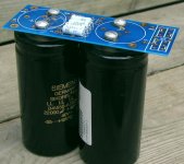
No traces need to be cut, just drill proper holes and remove solder mask.
The board you see in a picture above had the holes already, as it was designed for F3 amp where only single positive voltage PS board could be used, hence I made it suitable for screw mount caps which usually come in larger size.
The board you see in a picture above had the holes already, as it was designed for F3 amp where only single positive voltage PS board could be used, hence I made it suitable for screw mount caps which usually come in larger size.
Heat sinks for rectifiers?
Peter,
There is discussion about using heat sinks for the rectifiers in the F5 (and I guess any other application for that matter) due to a diminution of performance due to heat.
Do you find that the rectifiers heat up in your application?
Do you have an opinion on this? As always, I would be interested in hearing what you think.
Thanks,
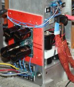
I didn't even consider using rectifiers without heatsinking, so it's hard for me to say how hot they normall run. My PS pcbs allow mounting rectifiers directly on a chassis, which I find more practical than additional heatsinks. Picture below shows one of my (temporary) test setups:
Attachments

Peter
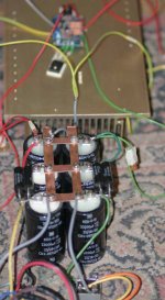
would you please advise best way to do gnd connections using your F5 pcbs
I ask because I got ground loop issue although no connection on input and even using just one amp pcb
my setup - gnd Input from rca - gnd pad of F5 pcb
rails gnd pad of F5 pcb Is fed from gnd of PSU filter which can be seen with yellow wire
brown wire goes to gnd binding post
http://www.diyaudio.com/forums/attachment.php?s=&postid=1807410&stamp=1240254247
Is there a need for "matching" rectifiers?
Peter,
Now for another question:
there was something said about matching rectifier diodes for bridges-
is this worth the trouble AND
can one do this with a multimeter?
I "measured" a few with my multimeter on the diode setting and could not get a repeatable value.
If this is a good idea would you recommend a method?
AS ALWAYS,
Thanks,
I don't think this is worth pursuing. If the diodes come from a same packaging, chances are they are pretty well matched anyway. I never match diodes.
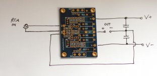
There is basically only one way to do it and it shouldn't produce any ground loops:
samoloko said:Peter
would you please advise best way to do gnd connections using your F5 pcbs
There is basically only one way to do it and it shouldn't produce any ground loops:
Attachments
Maybe you could post a picture of your setup?
The missing parts in my previous schematic are rectifiers which are connected as described here: http://www.diyaudio.com/forums/attachment.php?s=&postid=1804599&stamp=1239931785
The grounds from rectifiers go to the common point on filter caps.
The missing parts in my previous schematic are rectifiers which are connected as described here: http://www.diyaudio.com/forums/attachment.php?s=&postid=1804599&stamp=1239931785
The grounds from rectifiers go to the common point on filter caps.
thx Peter
at first I had connected both yellow wires to the gnd of last filter cap
http://www.diyaudio.com/forums/showthread.php?postid=1807410#post1807410
but after Andrew T recommendation - one post ubove I did extension with gray wire
one last thing - I don't have safety network - I only experiment at that point
- Status
- This old topic is closed. If you want to reopen this topic, contact a moderator using the "Report Post" button.
- Home
- Group Buys
- F5 pcb group buy...