Here's some pics;
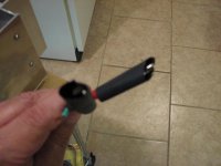
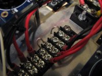
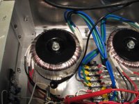
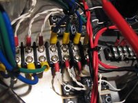
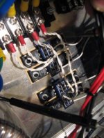
First is the temporary "plug" With alligators attached to clamp onto the transformer primaries, which can be seen connected together with temporary straps for the alligators to clamp onto. Next shot shows transformer and secondaries going to other terminal block, then next shot shows the white leads going to the diode boards. Measuring where the secondaries attach to the termonal block, each of the two pairs measures 17 volts, I dont think the variac was quite all the way up...
First is the temporary "plug" With alligators attached to clamp onto the transformer primaries, which can be seen connected together with temporary straps for the alligators to clamp onto. Next shot shows transformer and secondaries going to other terminal block, then next shot shows the white leads going to the diode boards. Measuring where the secondaries attach to the termonal block, each of the two pairs measures 17 volts, I dont think the variac was quite all the way up...
Attachments
50 volt measurment taken with black multimeter lead on the V-, and the red multimeter lead on the V+...
russellc
thats the problem. your feeding the boards ultimately two 22-25v connections.
Take one v- and one v-. The ground in the middle ties then together for return.
Your cool.

All output ground connections should go to the red spot id'd on peter's shot a few posts back. tie a wire down there and connect all Ground signals to it.
Solder a CL60 thermistor there, and attach that to chassis ground a IEC earth ground.
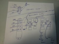
sorry, but I'm a little dense here, not sure what you mean by this? Could you describe where I went wrong by my crappy sketch?thats the problem. your feeding the boards ultimately two 22-25v connections.
Take one v- and one v-. The ground in the middle ties then together for return.
Your cool.
are you saying to ignore one set of secondaries? Sorry, I'm not understanding...
Russellc
50 volt measurment taken with black multimeter lead on the V-, and the red multimeter lead on the V+...
russellc
What are you getting when one lead is on V+ and the other on GND?
What are you getting when one lead is on V+ and the other on GND?
26 volts DC
Russellc
What are you getting when one lead is on V+ and the other on GND?
Is this how its supposed to be measured? ( red to V+ or V- and the other to ground) or from V+ and V-?
Russellc
50 volt measurment taken with black multimeter lead on the V-, and the red multimeter lead on the V+...
russellc
Is this how its supposed to be measured? ( red to V+ or V- and the other to ground) or from V+ and V-?
Russellc
yes.
I am looking to get into a new project. Are there boards still available? What are the current prices? Delivery costs are charged to Spain.
I am planning in building a pair of full mono blocks. How many boards of each should I need?
I'm running low on those boards but few are still available. I'm charging $5 shipping now: F5 info: http://www.diyaudio.com/forums/group-buys/140306-f5-pcb-group-buy.html
PS boards: http://www.diyaudio.com/forums/audio-sector/149672-universal-power-supply-pcb.html
For dual mono, you'll need one amp board and 2 PS boards.
yes.
Ah, thank you Tea Bag! I guess I just measured from the wrong points. Back on the launching pad it goes! Sorry to be so thick on this, i just dont want to throw the switch for disaster!
Russellc
500mv DC offset
I got one channel fired up and got both R 11 and R 12 to measure .59 but when I measured the DC offset at the speaker posts, it measures over 500 mv.
Before I just park it in the garage, anyone have any thoughts? Obviously something is very wrong. What would cause such a high number?
Russellc
I got one channel fired up and got both R 11 and R 12 to measure .59 but when I measured the DC offset at the speaker posts, it measures over 500 mv.
Before I just park it in the garage, anyone have any thoughts? Obviously something is very wrong. What would cause such a high number?
Russellc
You need to adjust both pots to get close to 0mV offset first, then bring them both up for proper bias.
That means, that with your 500mV offset, one pot has to go up, the other down, then both same way to bring bias to desired value.
I'm following what your saying, but if both are at .59, how do I turn one up without going over .59? Or should I take it down to .30 or so and go from there? I'll fidget with it some more, back shortly.
russellc
Turn one of the pots (you need to figure out which ) to get zero offset and lower bias.
Then turn them both, bit by bit, to get desired bias.
The voltage drop on source resistors will always be equal, just by balancing two trimpots properly you will get both the 0mV offset and 600mV voltage drop on resistors.
I use only 2 multimeters for adjustment: one is at the output the other at one of the source resistors; the voltage on the other resistor is always the same.
Turn one of the pots (you need to figure out which ) to get zero offset and lower bias.
Then turn them both, bit by bit, to get desired bias.
The voltage drop on source resistors will always be equal, just by balancing two trimpots properly you will get both the 0mV offset and 600mV voltage drop on resistors.
I use only 2 multimeters for adjustment: one is at the output the other at one of the source resistors; the voltage on the other resistor is always the same.
Yes, its working, I'm down to 5 Mv, I think I can 0 it out. I wouldnt have expected the circuit to work like that, but I turn one up and the other down, the Mv on the output goes down and the two resistors measurements are the same, but low. Now to bias it up. Thanks for the time to school me here, much appreciated.
Russellc
- Status
- This old topic is closed. If you want to reopen this topic, contact a moderator using the "Report Post" button.
- Home
- Group Buys
- F5 pcb group buy...