Strictly speaking it is not a cap multiplier. I can agree with that.
It was given that unfortunate name because of the similarity to the cap multiplier circuit that was referred to.
And then we can enter into an academic discussion as to whether it is a regulator, or voltage referenced emitter follower.
The term regulator has a different meaning for me.
But we probably shall not agree, so we should just leave it at that.
Patrick
Stixx does not know what he posted.
Yeah. Patrick is the originator of this thread, and he also hinted these modifications of the circuit to me. I drew the schematic and built it. It works fabulous.
Call it what you want and please stop the continuous wisecracking around here. Thank you.
The F5 is unbelieveably transparent, tonally perfectly balanced, has beautiful treble and tight and deep bass,
the best soundstage I ever had in my setup... the list goes on. I am speechless.
This is pure beauty.
Thank you Patrick.
That's very impressive, especially given your experience with many
headphone amps. BTW, what headphones did you use for your testing?
Cheers,
Dennis
Stixx does not know what he posted.
Why wait for him, it appears he does not understand why his sch is not a capacitor multiplier?
Yes, I saw your reply about his supply really not being a capacitor multiplier.
This nomenclature issue reminds me of a guy who asked for power supply advice. He was using a TL431 in two locations, in both cases with an external transistor. He seemed to believe that both were somehow open-loop regulators, that is, not using global feedback (viewed as bad). I pointed out that the arrangement for the positive supply was using the bipolar as part of the 431 feedback loop, and that was definitely global feedback---not to mention that the 431 is a complex feedback system by itself, with a band gap reference and feedback amplifier driving the shunt element. For the negative regulator it was simply an emitter follower. He seemed horrified when I said I could supply an arrangement with higher performance for the negative rail, and using the positive output as the reference for the negative. For him, this would look too much like global feedback---it was if he could hear the supposedly deleterious effects of feedback already.
The reason for using an "open loop" power supply has been explained here :
http://www.diyaudio.com/forums/pass-labs/271926-f5-headamp.html#post4288998
And it is not all down to the low ESR cap on the Vero board.
In fact, it even tripped the mains fuse of my lab PSU (which has NFB) multiple times.
Eventually I figured out how to get it to operate.
But it is too fiddly for public use.
I know there will be no issues with a emitter follower supply.
And the Zout is low enough at 150mA bias.
Patrick
That's very impressive, especially given your experience with many
headphone amps. BTW, what headphones did you use for your testing?
Thank you Dennis, it is indeed impressive. In audio you sometimes come to a point where you think " nah, it can't be much better...",
and then an F5 headamp comes around the corner (so to speak).
")
I was using Hifiman HE 500 and Sennheiser HD800 for testing, both with excellent results. The Senn is the more accurate of the two
but can be a tad problematic on some recordings... not so with the F5 HA.
Went through my entire repertoire of "test tracks", and every single one sounded a bit different than I was used to... especially
more open and more natural
> If typing just a few numbers is too much trouble, then forget it.
It took a lot more of my time to get you a Spice model to play with.
So you obvious did not get the point.
> I thought Stixx could answer the questions I addressed to him ....
Of course he can answer them all.
I won't jump it again. Don't worry.
Patrick
This would be unfortunate. Although I too sometimes like the simple answers, I do appreciate the more comprehensive efforts on your part (especially the spice model), which are in the long run much more valuable. So thank you Patrick.
> Although I too sometimes like the simple answers .....
http://www.diyaudio.com/forums/pass-labs/271926-f5-headamp-3.html#post4315990
Actually someone else sent me a PM to say he appreciated that I posted the SPICE file rather than the straight answer.
This is the DoItYourself that I am happy to support - to help you to help yourself.
Not spoon feeding.
Once you learn to use Spice, you can answer a whole lot of other questions yourself.
If that is too much trouble then this is for sure the wrong project for you.
Patrick
Last edited:
Not spoon feeding.
If that is too much trouble then this is for sure the wrong project for you
I'm not asking to be spoon fed from you or anyone else here.
If my resistor wattage question had been one that had been asked numerous times and answered numerous times, then I certainly could've understood your reluctance to answer it.
I'm not against learning LTSpice, but right now I just don't have the extra time to sit down and learn the program.
There'll always be some new program or software that one really should learn in order to design new circuits or modify existing ones.
Whether or not one wants to learn these programs is up to the individual.
I realize when it's all said n' done that you were actually trying to help me more by trying to get me to play around with the circuit in LTSpice vs. just giving the wattage rating of the 2 resistors.
For that as well as your other replies, I am grateful even though I took it the wrong way initially. For that I sincerely apologize.
I don't think it's the wrong project for me at all.
Are you going to start determining who your circuits are for and who they aren't...LOL...LOL?
Come on...if you think someone can't build this simple amplifier and get it working properly without having to learn LTSpice or use some "exotic" power supply, then you are mistaken.
I'm sure there are plenty of other power supplies that will do just fine.
Hi ammel68,
Actually it will only take about 15min of your time.
Download and install the program.
Linear Technology - Design Simulation and Device Models
Open the file from post #236
http://www.diyaudio.com/forums/atta...p-stixx-cap-multiplier-load-reg-amplitude.asc
Run (Click the "running man")
That should open up a new window that looks blank.
Now the option for "pick visible traces" will be available in the menu bar.
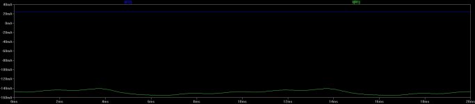
Clicking it will bring up an option screen. Highlight I(R1) and press "ok".
You should now see a waveform in the new screen that shows the current running through R1 (a max of around 156mA).
P=I*I*R=(0.156A)(0.156A)(8.2Ω)=0.2W, so 1/4W here.
Now for the fun part.
If you left click a part on the schematic you can change the value. Here I changed R2 to 1K. Now I=25mA, so you will need 3/4W if you do that. (R1 is still 8.2Ω)
Actually it will only take about 15min of your time.
Download and install the program.
Linear Technology - Design Simulation and Device Models
Open the file from post #236
http://www.diyaudio.com/forums/atta...p-stixx-cap-multiplier-load-reg-amplitude.asc
Run (Click the "running man")
That should open up a new window that looks blank.
Now the option for "pick visible traces" will be available in the menu bar.
Clicking it will bring up an option screen. Highlight I(R1) and press "ok".
You should now see a waveform in the new screen that shows the current running through R1 (a max of around 156mA).
P=I*I*R=(0.156A)(0.156A)(8.2Ω)=0.2W, so 1/4W here.
Now for the fun part.
If you left click a part on the schematic you can change the value. Here I changed R2 to 1K. Now I=25mA, so you will need 3/4W if you do that. (R1 is still 8.2Ω)
Attachments
Alazira, thank you for the quick tutorial.
I'll give it a try.
Ditto! Thanks.
I was asked by PM whether the F5-HA would work with certain proprietary power supply.
The simple but honest answer is I don't know. We have not tried them with the F5-HA.
The pragmatic answer is that those already tested in this thread will work.
They include the normal 7815/7915, LM317/337, and the Zener referenced cap multiplier.
More we have not tested, nor do we have any plans to.
That does not mean that they are not suitable or would not work.
If you know what you are doing, and want to try them out, by all means, and come back and tell us.
If you don't know what you are doing, and want to have proven solutions, then you should pick one of the above.
As Stixx reported, they all worked to his satisfaction.
http://www.diyaudio.com/forums/pass-labs/271926-f5-headamp-5.html#post4374209
Patrick
As Stixx reported, they all worked to his satisfaction
Correct... with a preference for the zener referenced cap multplier... subjectively.
Hi Stixx, i just checked out your website, and I'm Very impressed with your design talents. Your amps are better looking than most commercial offerings. Very inspiring for DIYers.
You have also convinced me I should build this F5. I rate my Dynalo, so this must be an impressive amp if it dethroned your Dynahi.
You have also convinced me I should build this F5. I rate my Dynalo, so this must be an impressive amp if it dethroned your Dynahi.
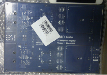
Oh wow, that looks like a nice, compact build! Looks very similar to post #29: http://www.diyaudio.com/forums/pass-labs/271926-f5-headamp.html#post4283872
Looks like there's room reserved for a crossfeed buffer...interesting.
If you need a tester, I'm game.
Looks like there's room reserved for a crossfeed buffer...interesting.
If you need a tester, I'm game.
It has quite a few refinements compared to post #29.
But still same size of 160 x 220mm, and will fit a 2107 case.
Aluminum chassis case enclosure amplifier chassis headphone box 212*70*257 mm | eBay
I shall test the PCB myself. I promised a friend to build one for him.
Patrick
But still same size of 160 x 220mm, and will fit a 2107 case.
Aluminum chassis case enclosure amplifier chassis headphone box 212*70*257 mm | eBay
I shall test the PCB myself. I promised a friend to build one for him.
Patrick
- Home
- Amplifiers
- Pass Labs
- F5 Headamp ?