Try both and tell us what your subjective preference.
OK, before ordering any of the Fairchilds, I just wanted to make sure they are a direct substitute for the 9610/610 devices without any changes to the circuit.
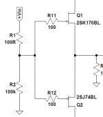
Assuming that your JFETs has Idss >= 8mA, no change required.
Bias is adjusted using R3, R4, for which I used 820R // 5k trimmer for the IRF's.
The Fairchilds has Vgs at 5.2V, slightly higher than the IRF's 4.2V.
So you might wish to order both 820R & 1k, just in case.
Costs you 50 cents extra.
Patrick
Bias is adjusted using R3, R4, for which I used 820R // 5k trimmer for the IRF's.
The Fairchilds has Vgs at 5.2V, slightly higher than the IRF's 4.2V.
So you might wish to order both 820R & 1k, just in case.
Costs you 50 cents extra.
Patrick
After doing this and that I finally came around to build a proper supply for my F5 headamp.
Finished the Nazar regs first (post #143, not tested yet) and then built a bipolar supply af capacitance multipliers
(similar to Rod Elliot's with a few tweaks from Patrick). Decided to run a little bit higher Vout and now have a nice
supply putting out +-16.4V.
Connected it to the F5 today and spent the next three hours with headphones on. This is my twelth self-built
headphone amplifier (actually given to me by EUVL), and seconds into the music I knew this is it. The supply is
very very quiet with NO background noise or hiss at all, and music is just flowing.
The F5 is unbelieveably transparent, tonally perfectly balanced, has beautiful treble and tight and deep bass,
the best soundstage I ever had in my setup... the list goes on. I am speechless.
This is pure beauty.
Thank you Patrick.
PS. Bye bye tube amps, even the Dynahi was easily proved better. Quite an achievement")
Finished the Nazar regs first (post #143, not tested yet) and then built a bipolar supply af capacitance multipliers
(similar to Rod Elliot's with a few tweaks from Patrick). Decided to run a little bit higher Vout and now have a nice
supply putting out +-16.4V.
Connected it to the F5 today and spent the next three hours with headphones on. This is my twelth self-built
headphone amplifier (actually given to me by EUVL), and seconds into the music I knew this is it. The supply is
very very quiet with NO background noise or hiss at all, and music is just flowing.
The F5 is unbelieveably transparent, tonally perfectly balanced, has beautiful treble and tight and deep bass,
the best soundstage I ever had in my setup... the list goes on. I am speechless.
This is pure beauty.
Thank you Patrick.
PS. Bye bye tube amps, even the Dynahi was easily proved better. Quite an achievement
Last edited:
After doing this and that I finally came around to build a proper supply for my F5 headamp.
Finished the Nazar regs first (post #143, not tested yet) and then built a bipolar supply af capacitance multipliers
(similar to Rod Elliot's with a few tweaks from Patrick). Decided to run a little bit higher Vout and now have a nice
supply putting out +-16.4V.
Can you share a schematic and any other details of your final power supply?
Thanks...
@P. coming...Some pictures perhaps ?
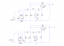
@Ammel: I can post schematics of the cap multiplier as I built it tonight (our time). Hope Patrick doesn't mind. It's basically a lot of capacitance to start with (CRC 10000uF - 8R2 - 10000uF) and then the multiplier. Amazingly quiet supply.
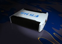
PS. Teaser of the case attached... based on Fischer SK56 sinks (rendering)
Attachments
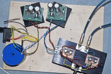
Schematics of the cap multipliers attached. I am using a string of two LM329 and two red Led's in my build to arrive at 16.4V.
The transformer is a custom wound toroid with two shields and 2x18.5V, so plenty of overhead. No mechanical hum, no noise.
Sinks of the supplies are temporary of course, didn't have anything better at hand Final wiring will also be nice and tidy.
.
The transformer is a custom wound toroid with two shields and 2x18.5V, so plenty of overhead. No mechanical hum, no noise.
Sinks of the supplies are temporary of course, didn't have anything better at hand
Final wiring will also be nice and tidy..
Attachments
Last edited:
Thank you Stixx for posting your schematic and photos.
Your circuit actually looks easier to build than I first imagined.
A few questions:
1) Are the LEDs 3mm or 5mm red?
2) What are the wattage ratings for the 2 resistors?
3) Is E452 a current regulatory diode?
E-452 Semitec | Mouser
4) Since I can not get a 18.5V transformer, would any changes need to be made to use a standard 18V transformer?
Thanks...
> 1) Are the LEDs 3mm or 5mm red?
Same. No difference.
> 2) What are the wattage ratings for the 2 resistors?
Time to learn to use LTSPice, as Stixx did.
> 3) Is E452 a current regulatory diode?
Yes.
> 4) Since I can not get a 18.5V transformer, would any changes need to be made to use a standard 18V transformer?
No change if you do not want more than +/-18V rails.
> if using this amplifier with say a 10K volume pot on the inputs, are both R1 and R2 needed, or just R2 to establish the input impedance of the amp?
Just R2, close to the JFETs.
Patrick
By inserting the Zeners and LEDs you have created a voltage regulator rather than a capacitance multiplier.Schematics of the cap multipliers attached. I am using a string of two LM329 and two red Led's in my build to arrive at 16.4V.
The transformer is a custom wound toroid with two shields and 2x18.5V, so plenty of overhead. No mechanical hum, no noise.
Sinks of the supplies are temporary of course, didn't have anything better at hand
.
Time to learn to use LTSPice, as Stixx did.
Patrick
I don't think so, but I do appreciate your replies to my other questions.
If typing just a few numbers is too much trouble, then forget it.
Resistor wattage is far from "rocket science" and I have lots of them, so I'll start with something higher wattage just to be safe should I ever decide to try this power supply.
I thought Stixx could answer the questions I addressed to him about his power supply, but obviously that wasn't the case.
> If typing just a few numbers is too much trouble, then forget it.
It took a lot more of my time to get you a Spice model to play with.
So you obvious did not get the point.
> I thought Stixx could answer the questions I addressed to him ....
Of course he can answer them all.
I won't jump it again. Don't worry.
Patrick
It took a lot more of my time to get you a Spice model to play with.
So you obvious did not get the point.
> I thought Stixx could answer the questions I addressed to him ....
Of course he can answer them all.
I won't jump it again. Don't worry.
Patrick
Schematics of the cap multipliers attached. I am using a string of two LM329 and two red Led's in my build to arrive at 16.4V. .................
By inserting the Zeners and LEDs you have created a voltage regulator rather than a capacitance multiplier.
Stixx does not know what he posted..................................I thought Stixx could answer the questions I addressed to him about his power supply,..............
Why wait for him, it appears he does not understand why his sch is not a capacitor multiplier?
read this again
"I am using a string of two LM329 and two red Led's in my build to arrive at 16.4V"
That makes it a voltage regulator.
Last edited:
- Home
- Amplifiers
- Pass Labs
- F5 Headamp ?