On the good channel, the resistance over the pot seems to be set to about 60ohm.
On the bad channel, there is something strange, yes. The resistance seems to drift upwards! 😱 With pots dialed to max it ends up to stabilize around 444ohm on one and 500ohm on the other. But something makes it to drift.
What's wrong there?
On the bad channel, there is something strange, yes. The resistance seems to drift upwards! 😱 With pots dialed to max it ends up to stabilize around 444ohm on one and 500ohm on the other. But something makes it to drift.
What's wrong there?
Your approach to the problem is wrong.... What's wrong there?
You measure what's convenient to you and not what is needed.
You were advised to measure the voltage drop accros JFETs' Source resistors. That would reveal the Id through JFETs and we would have a clue what's wrong or what to do next.
Also, I have an impression that you didn't read/understand the F5 article. You got to cover the basic stuff...
No, this is not my profession. There are plenty of things I don't understand, no matter how many times I read them. To compensate me being a total idiot asking dumb questions in this area, there's other stuff in life which I master pretty nicely.
I measured the pots first, as suggested in here. It was the easy way out, if that would've told something. Did it? I don't know: not to me, except that channels behave differently in regard to resistance drifting with the power off.
I asked from you in the other thread about how to measure across R1 and R2 what you suggested. As you already pinpointed correctly, I'm an ignorant fool unable to understand what I'm reading when it comes to electoronics, but I rather ask than jump head first. With offset at zero (bias ~0.06V) or higher voltage dialed in - no matter the off-set?
Even tho I cannot access R1 and R2 directly, I can measure the voltage by attaching DMM on R5's / R6's leg and ground.
Do you -or anyone- have any comment on the resistance drifting? With power off that is. No, I don't understand this phenomena either.
Of course, if there are still boards and component kits available, I can order a new set, trash this one, and hope I'll get as lucky as I was with the first board, without understanding the stuff you master. Anyway, this has been a long project already now.
^Went thru the joints with my soldering iron after taking the board off the last time. It'd be fun actually if that was the case: I've always stated that anyone who can weld good, can certainly solder, but let's see... 😀
That's what I'm afraid of. That's why I measured the mosfet resistances, but those values tell nothing to me, except that none was zero. 😀
Let's see: if it was a joint problem, it should be now revealed while I set up for the measurements juma suggested needed.
Let's see: if it was a joint problem, it should be now revealed while I set up for the measurements juma suggested needed.
Begin by replacing the both the pot bypass resistors (R3, R4) with more resistance. If they are 2.2k now, go to about 4.4k or so. This will most likely fix the low bias on the 'good' channel, allowing the full bias amount, and hopefully a bit more.
Hopefully, on the 'bad' channel, you will be able to get the circuit to behave more normally... I doubt you will get the full bias, but you might be able to get .2 or something with zero offset. If this is the case, just continue to make the value of the bypass resistor (R3 or R4, depending on which channel) bigger (more ohms). My first F5, with TechDIY parts, has one pot with 6.6k in the bypass position! It biases fine and sounds great.
Some photos from my build thread where I lifted one of the bias resistors and added more in series --
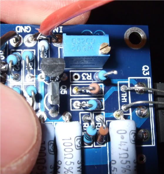
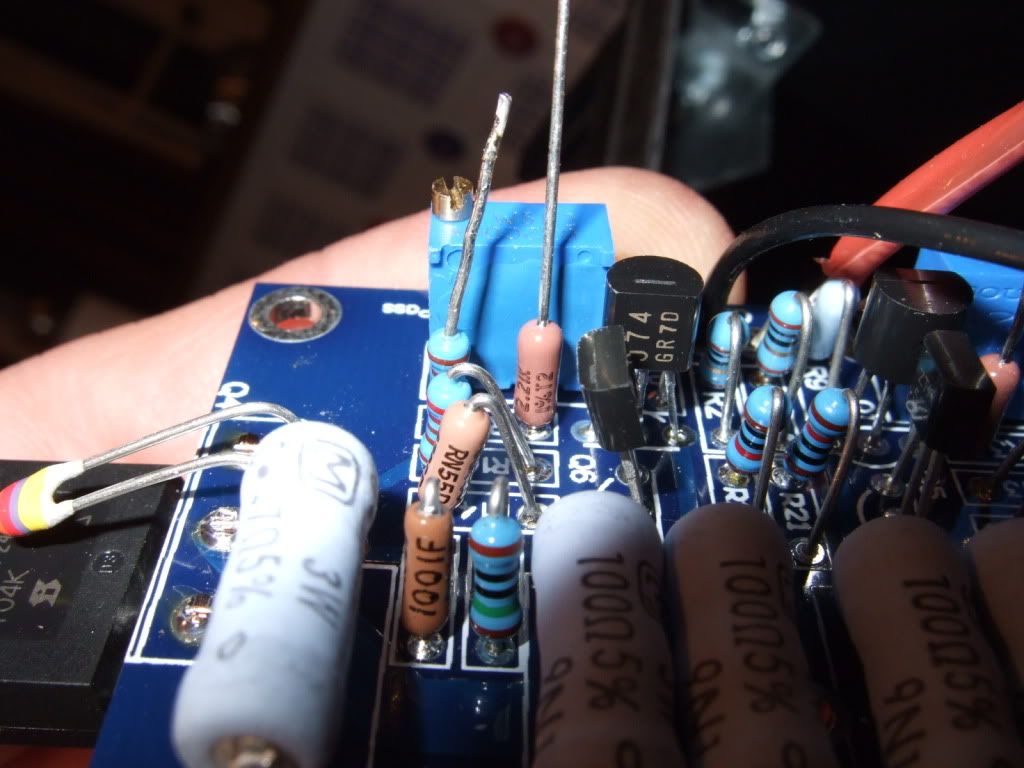
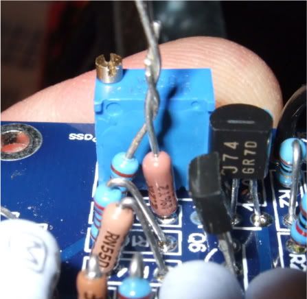
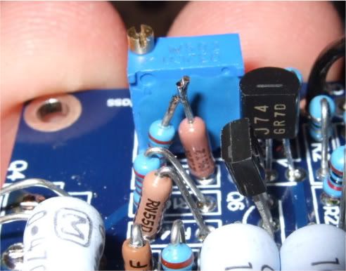
Of course, you can just replace the whole resistor instead of adding a component or two, I just happened to have a bunch of 2.2k resistors on hand.
Hopefully, on the 'bad' channel, you will be able to get the circuit to behave more normally... I doubt you will get the full bias, but you might be able to get .2 or something with zero offset. If this is the case, just continue to make the value of the bypass resistor (R3 or R4, depending on which channel) bigger (more ohms). My first F5, with TechDIY parts, has one pot with 6.6k in the bypass position! It biases fine and sounds great.
Some photos from my build thread where I lifted one of the bias resistors and added more in series --
Of course, you can just replace the whole resistor instead of adding a component or two, I just happened to have a bunch of 2.2k resistors on hand.
Last edited:
Ok, went up with the pots this time as per follows in order to do the measurement juma suggested last night:
mV
R11____0___0,2__1,0__2.5__3.0_______216__292__386__400
R12____0___0,0__0,0__0.4__1.1(dial)_213__290__384__399
offset_10___23___76__134__125_______209__212__228__229
R1_________________________________________________75.7
R2__________________________________________________2.9
Thus, poking with the soldering iron changed nothing.
Even tho I know nothing, I'd guess 75.7 vs 2.9 indicates some problem. Didn't see a reason to climb any further in voltage from there, since -per experience this far- offset does not change much from that.
What next?
Last edited:
Begin by replacing the both the pot bypass resistors (R3, R4) with more resistance. If they are 2.2k now, go to about 4.4k or so. This will most likely fix the low bias on the 'good' channel, allowing the full bias amount, and hopefully a bit more.
There is no any problem with the good channel. I just didn't want to dial it above 0.6V before both channels done.
Is the problem within mosfets? I.e. if I replace them with good ones, problem gone? How to know what's good and what's bad?Hopefully, on the 'bad' channel, you will be able to get the circuit to behave more normally... I doubt you will get the full bias, but you might be able to get .2 or something with zero offset. If this is the case, just continue to make the value of the bypass resistor (R3 or R4, depending on which channel) bigger (more ohms). My first F5, with TechDIY parts, has one pot with 6.6k in the bypass position! It biases fine and sounds great.
TechDIY was supplying GR grade Jfets, making the required bias resistance greater.
If you can get a little past full bias with zero offset, say .7, then don't mess with changing the resistor on that side. (and adjust to .6)
But on the 'bad' side, do start to increase the resistor and see what happens. Also double triple check for a bad solder joint.
If you can get a little past full bias with zero offset, say .7, then don't mess with changing the resistor on that side. (and adjust to .6)
But on the 'bad' side, do start to increase the resistor and see what happens. Also double triple check for a bad solder joint.
1.
desolder mosfets from faulty channel pcb
2. power up - measure voltage across source resistors of input Jfets
3.power off
4. write here what you measured
desolder mosfets from faulty channel pcb
2. power up - measure voltage across source resistors of input Jfets
3.power off
4. write here what you measured
Ok, shall do. Altho I am more than just a bit worried about the desoldering of those... Is it likely that mosfets are bad/gone? If I should even try to save them instead of clipping the legs...1.desolder mosfets from faulty channel pcb
2. power up - measure voltage across source resistors of input Jfets
3.power off
4. write here what you measured
Yes, ones I got are GR. I have also a bunch of BL grade Jfets in hand. Should I (have) rather use(d) them?TechDIY was supplying GR grade Jfets, making the required bias resistance greater.
Yes, ones I got are GR. I have also a bunch of BL grade Jfets in hand. Should I (have) rather use(d) them?
Nah. Just increase the resistance across the pot. Easy-peasy. 😀 😀 😀
I could replace these as well, since much more demanding desoldering seems to come into play per Zen Mod adviced route, IF there really is something to gain by using BL units. Is there?Nah. Just increase the resistance across the pot. Easy-peasy. 😀 😀 😀
I guess I should do some sorting for the jfets in this case - I think I've seen something somewhere... Well, I don't find it. And if I find it, it's likely per now that I won't get it...
Well, I don't know, anything about anything. I ordered a ready set to solder. It was fun to do the mechanics with the box and legs, soldering was nice, as well as wiring considerations. Plug and play; electonics to be neatly put into a nice box. Now I'm facing measurements I don't understand, risk to damage the board within desoldering... This was supposed to be an easy way to get into amp building... Where did the fun part go?
I have a sneaky suspicion you are literally 2 resistors away from a working amp. Increase the resistance across the pot in the 'bad' channel if only to troubleshoot. If the amp biases with the bigger resistor and tests good, you will know that you have no other problems.
Right. This shows us that 2sk170 has Id=7.5mA and 2sj74 hardly conducts (Id=0.29mA). It's about 7 times lower than allowed by datasheet for GR range. If you didn't make measuring mistake, that JFET is gone bad or R2 is not 10 Ohms or feedback resistors are wrong value......
R1_________________________________________________75.7
R2__________________________________________________2.9
Even tho I know nothing, I'd guess 75.7 vs 2.9 indicates some problem. ...
Plenty of options what to do. Thanks everybody! 🙂
juma:
I'll measure once again. Is this value dependent on trimpot setting?
I'll check also all the values once more, altho checked multiple times already.
So.. You'd conclude that the problem must be in jfet? If all the resistors are per schematics. Not in mosfet? I.e. is this check exclusive for jfets? If yes.. I guess I better replace the jfets (both) with the BL ones which I luckily just happen to have.
If the jfet is the root for all the evil.. To avoid the same happening again.. What are the probable reasons it being broken? Too much heat in soldering? Component already faulty when delivered? Something else I should be aware of? Some special precaution I should take with BLs?
JFET's Id is not dependent on trimpot. Id is a function of Vgs (when Vds > 5V which is the case here).
To exclude the MOSFETs from the equation, do as Zen Mod wrote in post #112.
Then check you MOSFETs:
http://firstwatt.com/pdf/art_matching.pdf
Use BL grade JFETs.
To exclude the MOSFETs from the equation, do as Zen Mod wrote in post #112.
Then check you MOSFETs:
http://firstwatt.com/pdf/art_matching.pdf
Use BL grade JFETs.
TechDIY was supplying GR grade Jfets, making the required bias resistance greater.
If you can get a little past full bias with zero offset, say .7, then don't mess with changing the resistor on that side. (and adjust to .6)
But on the 'bad' side, do start to increase the resistor and see what happens. Also double triple check for a bad solder joint.
You got to be kidding me! I have been banging my head over this "easy" project for a month. This is my problem...
- Status
- Not open for further replies.
- Home
- Amplifiers
- Pass Labs
- F5 Bias Problem