Since you got it working could you share . I take it the number are low as to distortion .After all this time I got it to work. Please ignore my request.
Jim

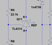
The model for the TL431 is included in the simulation I attached above but here is a copy for easy use.
.subckt TL431ED K A ADJ
Q1 K ADJ N005 0 QN_ED
Q7 N003 N003 N001 0 QP_ED
D1 A N004 D_ED
Q8 N004 N003 N002 0 QP_ED
R4 N005 N009 3.28k
R2 N009 N012 2.4k
R3 N009 N010 7.2k
R1 N014 A 800
R5 N006 N011 4k
R7 K N001 800
R8 K N002 800
R6 N013 N012 1k
R9 N008 N007 150
R10 N008 A 10k
D2 A K D_ED
C1 K N004 10p
C2 N010 N011 20p
Q2 N012 N012 A 0 QN_ED area=1.2
Q3 N010 N012 N014 0 QN_ED area=2.2
Q5 N011 N010 A 0 QN_ED
Q9 K N004 N007 0 QN_ED
Q10 K N008 A 0 QN_ED area=5
Q4 N003 N005 N006 0 QN_ED
Q6 N004 N013 A 0 QN_ED area=0.5
Q11 N004 N004 ADJ 0 QN_ED
.model D D
.model NPN NPN
.model PNP PNP
.model QN_ED NPN(BF=140 Cje=1p Cjc=2p Rb=40 VAF=80 VAR=50 KF=3.2e-16 AF=1)
.model QP_ED PNP(BF=60 Cje=1p Cjc=3p Rb=80 VAF=70 VAR=40)
.MODEL D_ED D(Rs=5 CJ0=4.0p)
*
.backanno
.end
Jim
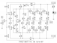
Here is my LTSpice simulation for the F4. This follows the schematic from the diyAudio Store. Please remember this is just a simulation based on imperfect models.
Thanks for sharing this .asc file. I had to go find a symbol which obviously is backwards. Also, when I run it, I get an error "mylib-jfet.lib" is missing"
1. Can you share your symbol file for the TL431?
2. Can you share your mylib-jfet.lib file?
Attachments
You need to flip the TL431. I'm not on my computer so this is just from a faulty memory. Select the TL431 by clicking on it. Press "e" to flip it. My libraries have way too many errors to go public. Learn how to create your own in the LTSpice thread by Mooly. It's a sticky in the Software subforum.
Jim
Jim
I checked. It is Ctrl E you need to press to flip the item selected.
Thanks. I did get it flipped. That required to pull down Edit ->Move then the device can be selected. Just clicking on the placed device did not select it.
Thank you for sharing your F4 circuit. I appreciate that you shared it.
As posted, your circuit will only run on your PC with your .lib files. After some reading, it appears that there is a way to make the circuit portable. I will work on removing the non-portability stuff and try to make it portable and able to run on my PC.
best regards,
Attached is a zip with the modified circuit with the JFET models embedded on the circuit and it runs.
I deleted the zener diodes. You can add them back if you find one with a model. They are not needed for DC operating point analysis which is what I want.
The TL431 files should be in the directory where the .asc file is. You may also need the TL431 files in your \lib\sub and \lib\sym\ directories.
I deleted the zener diodes. You can add them back if you find one with a model. They are not needed for DC operating point analysis which is what I want.
The TL431 files should be in the directory where the .asc file is. You may also need the TL431 files in your \lib\sub and \lib\sym\ directories.
Attachments
Looks like the exicon models are quite worse than the hitachi ones, so my simulations are a bit unconclusive.
What circuit? What models?
What circuit? What models?
Yours.
The models I found here. I will attach them.
Attachments
404 Not Found
This version bootstraps the front end so that the JFETs only
see about 1/2 the voltage swing. It improves THD very slightly,
gets a tad more output swing, and it also extends the bandwidth
a bit. With a proper setup, I get about -3dB at 1 MHz, with a
very good looking 100 KHz square wave.
Did anyone save this schematic from 11 years ago?
- Home
- Amplifiers
- Pass Labs
- F4 power amplifier