iquam,
power supply complication... multiple supply but same power draw as f4.
drive circuitry...maybe a transformer like f6 or something...? i had the idea of simply driving it with the D1.nice for low wattage speakers.
zen mod,
n is simply for n-ch mosfet.
check that Juma version he posted, it s pretty much similar.
Transformer coupling with +/-20V swings is probably not a good idea. I could be wrong, but none of the line transformers are suitable for that.iquam,
power supply complication... multiple supply but same power draw as f4.
drive circuitry...maybe a transformer like f6 or something...? i had the idea of simply driving it with the D1.nice for low wattage speakers.
zen mod,
n is simply for n-ch mosfet.
check that Juma version he posted, it s pretty much similar.
I was wrong. That is an interesting transformer, but the distortion might be a problem and the 1:5.6 turns ratio means a 1:31.4 impedance ratio, requiring a pretty low impedance driver to handle the MOSFET gate capacitances. OTOH, putting all of the primary windings in series and secondary windings in parallel gives a turns ratio of 1:1.4 and an impedence ratio of 1:2 which would be easy to drive.This just happens to be one I have. Check the max levels at the bottom of the page...
And, there are others...
Last edited:
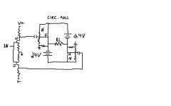
Hello Zen Mod. I hope that you are having a pleasant holiday. The schematic attendant to your post showed "a Flea Watt Integrated" amp. Please exemplify it. Thank you.this one ?
Best regards.
without stepping in Pa's IP barbwired yard , I can say - look in thread called something as Magma front end for F4
I think few capable xformers are mentioned there
though , not that xformers are sole way to feed da circlotron
issue beaten to death by toob guys , Atmasphere and such
all one need is phase splitter with some cojones
I think few capable xformers are mentioned there
though , not that xformers are sole way to feed da circlotron
issue beaten to death by toob guys , Atmasphere and such
all one need is phase splitter with some cojones
Got the post. Thankswithout stepping in Pa's IP barbwired yard , I can say - look in thread called something asMagma front end for F4
I think few capable xformers are mentioned there
though , not that xformers are sole way to feed da circlotron
issue beaten to death by toob guys , Atmasphere and such
all one need is phase splitter with some cojones
N.B. Also the terms "Flea Integrated Amps' and explanation appeared in th F4 Manual on page 4
Last edited:
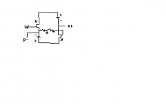
here strikes originality again!
No, it won't work.
The circuit you drew produces signals that are in phase one with another.
To drive the circlotron you need signals out of phase (180 degrees one from another).
pidesd,
Still no cigar, that won't work (it's no shortcut to symmetrical excitation).
And outputs need reference to GND too.
BTW, for yours and ours sake please use at least this: Invalid Request
")
Still no cigar, that won't work (it's no shortcut to symmetrical excitation).
And outputs need reference to GND too.
BTW, for yours and ours sake please use at least this: Invalid Request

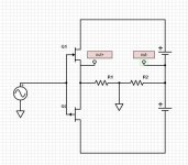
if the goal is to have minimum even harmonics at the speaker,would it make sense to use a line level splitter like attatched, with low even harmonics numbers, and then feed it to a complete symetric path to the speaker(for example, balanced bride of zen+circlotron follower) ?
as opposed to say, feed a line level signal to a scaled down son of zen with one input grounded,or an opamp-splitter (like juma did), to generate a balanced signal?
as opposed to say, feed a line level signal to a scaled down son of zen with one input grounded,or an opamp-splitter (like juma did), to generate a balanced signal?
Attachments
Last edited:
I purchased a DIYAudio Store Deluxe 4U Chassis sometime ago with the plan to used it for another F4 build. I have been slowly accumulating parts to complete the build and I am now getting around to putting it together.
Apparently, I did not pay sufficient attention to the hole drilling and tapping layout. For any amplifier PCB with the MOSFETs along only one edge, for best heat removal the MOSFET centers should be slightly below the center line of the heatsink. The Deluxe Store 4U heatsinks place the MOSFET centers about 32% (2.1") from the bottom of the heatsink. I have not yet run the NatSink simulation program for that heatsink to determine how much that positioning degrades the performance. I was already concerned that these heatsinks might be insufficent for the F4 at 1.3A bias per channel.
Has anyone out there used the Store Deluxe Store 4U chassis for an F4?
- Home
- Amplifiers
- Pass Labs
- F4 power amplifier