This particular application on a Zener diode doesn't appear to be sensitive to Zener noise. I did an LTSpice simulation with a 1mV sine generator in series with the Zener, and a zero volt input to the preamp. The result was 5uV of the Zener "noise" appearing in the output.
Last edited:
Curllian-F4 build and measurements
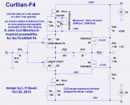
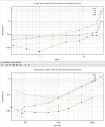
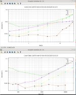
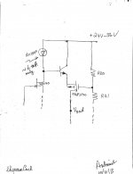
I did some measurements of the Curllian-F4 folded cascode preamp for the F4, using the schematic shown below. The input JFETs have an Idss of approximately 5ma, and gm of about 30mS at Idss. Shown are watt and frequency sweeps at 23V rails and 32V rails. The 32V rails look very good. THD might be improved by adjusting the cascode gate resistor divider for the 32V rails.
I have not yet done any testing in the F4.
Attachments
Great to know this approach to limit SOA of input FETs is noiseless.This particular application on a Zener diode doesn't appear to be sensitive to Zener noise. I did an LTSpice simulation with a 1mV sine generator in series with the Zener, and a zero volt input to the preamp. The result was 5uV of the Zener "noise" appearing in the output.
Last edited:
Please clarify the plots of THD versus output power. The preamp is not capable of 10 W or even 1 W power output. Maybe you are saying the preamp drives an F4 [voltage gain of 1 ?] loaded with 8 Ohms, such that the THD of the preamp is for its output voltages which allows F4 to give 1 and 10 W of output power.I did some measurements of the Curllian-F4 folded cascode preamp for the F4, using the schematic shown below. The input JFETs have an Idss of approximately 5ma, and gm of about 30mS at Idss. Shown are watt and frequency sweeps at 23V rails and 32V rails. The 32V rails look very good. THD might be improved by adjusting the cascode gate resistor divider for the 32V rails.
I have not yet done any testing in the F4.
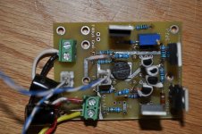
PCB looks great.
The Watts figure in those plots correspond to driving a 8 ohms load on the F4. Thus, 1 watts out corresponds to 4 volts peak, and 25 watts out corresponds to 20volts peak. I probably should show Vout in the plots rather than Watts.Please clarify the plots of THD versus output power. The preamp is not capable of 10 W or even 1 W power output. Maybe you are saying the preamp drives an F4 [voltage gain of 1 ?] loaded with 8 Ohms, such that the THD of the preamp is for its output voltages which allows F4 to give 1 and 10 W of output power.
PCB looks great.
Last edited:
Thank you for the clear answer.The Watts figure in those plots correspond to driving a 8 ohms load on the F4. Thus, 1 watts out corresponds to 4 volts peak, and 25 watts out corresponds to 20volts peak. I probably show Vout in the plots rather than Watts.
Keep in mind that my "conclusion" about the Zener noise in the folded cascode is based only on simulations, not actual measurement or listening tests. But, I suspect the conclusion is mostly correct.Great to know this approach to limit SOA of input FETs is noiseless.
I see on the pcb that you did not use zeners but doubled up on the JFETs. Thanks.Keep in mind that my "conclusion" about the Zener noise in the folded cascode is based only on simulations, not actual measurement or listening tests. But, I suspect the conclusion is mostly correct.
My bench supplies deliver 32V max. The JFETs had an Idss of about 5ma, and the biasing was such that their maximum Vds is about 27V, which is a little higher than the J74 wants to see, but ok for testing. The JFET average power dissipation is about 125mW each. With "optimal" biasing and 36V rails, the Zeners (or cascodes) are needed.I see on the pcb that you did not use zeners but doubled up on the JFETs. Thanks.
I find the measurements of Curllian-F4 THD-vs-freq are somewhat disappointing. I suspect that the primary problem is with the capacitances of the output MOSFETs. Can anyone recommend alternative complementary FETs, with low capacitances, that can handle Vds of 50V, and at least 2 watts power dissipation?
I have studied the datasheets for them. The capacitances do not appear to be any better, perhaps worse. I need to look closer, perhaps lambda (Early effect) is better with them.IRF610 / IRF9610?
The other thing I should look at it increasing the rails by a lot more, keeping the JFET voltages withing SOA. Simulations show that helps considerably. Power dissipation in the output FETs should be too much of an issue.
Another option is to incrase the class-A bias in the output fets. I haven't tested that.
I might have two each of those. It is worth a try. Too bad nothing as good is manufactured today.
Great minds think alike.Sorry for not seeing the postings before, may be too early in the morning....
Another option maybe to charge up the capacitances faster with a buffer [bjt] as shown in the attached for the positive part of the circuit.I find the measurements of Curllian-F4 THD-vs-freq are somewhat disappointing. I suspect that the primary problem is with the capacitances of the output MOSFETs. Can anyone recommend alternative complementary FETs, with low capacitances, that can handle Vds of 50V, and at least 2 watts power dissipation?
Attachments
Hello all you fine Pass-People! 
Sherman, set the Wayback machine for Ought-Eight. That is when I first purchased the Peter Daniels F4 boards and some of the parts for an DIY F4 project. I finally got started in earnest this past year. I've had many bumps and bruises, including a REALLY FUGLY chassis (building amps from scratch turns out NOT to be my forte') and a serious mistake with the PD power supply board that required me to P2P wire the power supply. In addition, I had all the newbie issues, including the latest--an unnoticed slipped ground, that caused me undue pain and suffering.
Why am I telling you all this? Well, tonight the F4ugly makes music! (That is the official name of my new amp. It deserves it too.) And I could not have done it with out nearly every one of the posts in this thread. So thank you all...I think
I still have to cram all of it in the "enclosure", test a bit more, then try it out with my big tube amp, but the all-important Smoke Test is done! Once I get it completely encased in the unfortunateness I call a case, I will post a picture. After all, I think my amp can easily win the least coveted title of the "Fugliest F4 in the World".
Cheers,
Gary
Sherman, set the Wayback machine for Ought-Eight. That is when I first purchased the Peter Daniels F4 boards and some of the parts for an DIY F4 project. I finally got started in earnest this past year. I've had many bumps and bruises, including a REALLY FUGLY chassis (building amps from scratch turns out NOT to be my forte') and a serious mistake with the PD power supply board that required me to P2P wire the power supply. In addition, I had all the newbie issues, including the latest--an unnoticed slipped ground, that caused me undue pain and suffering.
Why am I telling you all this? Well, tonight the F4ugly makes music! (That is the official name of my new amp. It deserves it too.) And I could not have done it with out nearly every one of the posts in this thread.
So thank you all...I thinkI still have to cram all of it in the "enclosure", test a bit more, then try it out with my big tube amp, but the all-important Smoke Test is done! Once I get it completely encased in the unfortunateness I call a case, I will post a picture. After all, I think my amp can easily win the least coveted title of the "Fugliest F4 in the World".
Cheers,
Gary
- Home
- Amplifiers
- Pass Labs
- F4 power amplifier