........
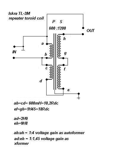
Correct me if I'm mistaken, ZM

I first posted gif , but it was unreadable
so moi edited - posted jpg this time
and I think colors are as on sketch I posted and , you're right
never mind , you gave recipe , colors are boring details

Attachments
Last edited:
two things , unfortunately : I'm not Pa
My spiritual leader, from the small state of Butane in the Himalayas, told me i should call you Nutpa.
(i just met him at the gas station, so i wanted to check if it's ok with you)
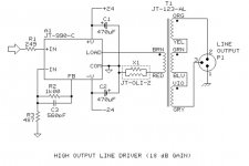
Hooked up the 4 Jensen JT-123-ALCF transformes wired as Nelson and Choky pointed out in posts 3399 and 3400 to my F4 headphone board.
I lifted R3 and R4 on the version 2 boards currently in the DIYAudio store on the cap side. I connected both leads to the transformer input (grey/brown)
The output was connected to the F4 board where R3 was lifted and the ground was also connected to the F4 board.
The sound is absolutely superb !!!!
 Have listened to Etta James, Eva Cassidy, Nina Simone, Phoebe Snow, Judy Collins, Doug McCloud, Laura Nyro and Van Morrison. Voices are amazing as is sound stage. Plenty of detail and outrageous bass. No problem driving the my HiFiMan 500s
Thanks Nelson and Choky for the help. Choky I see why you like the M2 !!!
Should I call mine a M2F4headphone amp?
Might have to build a SE version to drive the Ravens in my system.
Best
Bob
I lifted R3 and R4 on the version 2 boards currently in the DIYAudio store on the cap side. I connected both leads to the transformer input (grey/brown)
The output was connected to the F4 board where R3 was lifted and the ground was also connected to the F4 board.
The sound is absolutely superb !!!!
Thanks Nelson and Choky for the help. Choky I see why you like the M2 !!!
Should I call mine a M2F4headphone amp?
Might have to build a SE version to drive the Ravens in my system.
Best
Bob
awesome. I have 4 of the Sowters coming. I will try SE, but have plans for something else. Usually if ZM or Nelson suggest something, It is worth trying for no other reason than learning.
You are absolutely right. I learned a great deal from doing this !!!!!
Crippled F4 with BA3
I have yet finished with the chassis but am excited to test it out my new crippled F4 with BA3. It is singing now.
However the bias of some transistors especially the set of IRF240 were off by 10-40mV at around 200mV. I could have mismatched them and the method i used could be incorrect.
Using Conrad's heatsink, I could only touch the heatsink for 3 seconds. Question is whether the transistors will give up easily at the rate of dissipating this is going or should i lower the bias or add more heatsink?
An externally hosted image should be here but it was not working when we last tested it.
However the bias of some transistors especially the set of IRF240 were off by 10-40mV at around 200mV.
This value is not bad for the beginning.........!
Did you check that every pair has the 200mA......? Only to be sure.....
This value is not bad for the beginning.........!
Did you check that every pair has the 200mA......? Only to be sure.....
Generg, I biased the minimum at 200mV on the lowest value source resistors but the other resistors will read more then 200mV up to 230mV.
Is it advisable to change a tighter set of Vgs for the transistors? i already matched them to +/-0,02V beforehand.
I have placed the heatsink to vertical position and yes, the heat is now bearable. more than 5secs not a issue but still this is a hot amp.Zen Mod said:put them as intended - vertical , then try
This value is not bad for the beginning.........!
Did you check that every pair has the 200mA......? Only to be sure.....
Generg, I biased the minimum at 200mV on the lowest value source resistors but the other resistors will read more then 200mV up to 230mV.
Is it advisable to change a tighter set of Vgs for the transistors? i already matched them to +/-0,02V beforehand.
I have placed the heatsink to vertical position and yes, the heat is now bearable. more than 5secs not a issue but still this is a hot amp.Zen Mod said:put them as intended - vertical , then try
Generg, I biased the minimum at 200mV on the lowest value source resistors but the other resistors will read more then 200mV up to 230mV.
Is it advisable to change a tighter set of Vgs for the transistors? i already matched them to +/-0,02V beforehand.
I have placed the heatsink to vertical position and yes, the heat is now bearable. more than 5secs not a issue but still this is a hot amp.
Here comes a quotation from an article Nelson wrote 1993
"By placing 1ohm source resistors on each transistor, we can assure adequate current sharing for a fairly wide range of VGS. In Class A bias, we will be operating at about 200mA/device, which will place 0.2V across each source resistor. A variation in VGS will cause the bias to be unequally distributed between the devices. For example, for a 4.6V device in parallel with a 4.5V device, the first will run at about 160mA at 6W and the second at about 240mA at 9W."
You see how big the changes are from 4.6 to 4.5V Vgs!
In this article he also describes the method to change the resistors to counteract to the differences. I think it is not necessary in your case. But if you have the will and the time....
http://www.firstwatt.com/pdf/art_matching.pdf
When I compared some FW amps to my clones and they sounded much worse it was mostly the matching effort that could bring them nearer to Nelson Originals. (but never more than 80%)
Last edited:
Is it advisable to change a tighter set of Vgs for the transistors? i already matched them to +/-0,02V beforehand.
did you match them at 200mA like described in Nelson's article?
You could also follow his advice at look at one or two other points to get the more matched parts...
Thank you Generg, I will look through the articles and see if i can match the devices better next time. I shall not proceed further until i find matched parts. No point building a F4 if i cannot get the result at least 80% near to the orignal thing.  but how do you measure this aspect? It seems most F4 builder descibe the amp characteristic to that of water. Hope i can experience it too when i fine tune mine further.
.....the 80% is only a guess from my side! Saying that I succeeded getting the sound close to Nelson Original after some weeks...... 
In the meantime I was a bit depressive and thought to buy an original from the Master.....
and mind the Input J-fets too, I would suggest in this place an Idss of 10mA for the K170 and J74.
In the meantime I was a bit depressive and thought to buy an original from the Master.....
and mind the Input J-fets too, I would suggest in this place an Idss of 10mA for the K170 and J74.
- Home
- Amplifiers
- Pass Labs
- F4 power amplifier

