Well "decent" is a very subjective term. A high (my interpretation) level of global feedback will indeed control the output stage better but in my experience often also has other, less desirable effects. Maybe this circuit is different but I usually find I prefer solutions that use rather less global feedback.
well , if you take a look back at circuit I posted , you can see that JFets are having 100R in drains and that FE output node is pretty heavy loaded ....... that resistor pretty much influencing THD spectra
so , I resume - not having too much of OLG ......... however , I wouldn't go lower than that
so , I resume - not having too much of OLG ......... however , I wouldn't go lower than that
The problem is in the simulations. I have not yet built the low feedback version. The high feedback version runs really well.
I have run some simulations with "invented" pucks with matching transconductance (Kp) values. The distortion goes to below 0.001%, at 200Hz 4W 8R, even with zero feedback.
I have not been explicit about which FETs I am using since the purpose of this LTSpice file is to experiment with the FET model parameters as well as the other circuit parameters.
well , with perfect pair of pucks , I would need to invest my kidney and liver (both in great shape , tnx for asking) , to induce some 2nd
luckily , they aren't ideal , so some sweetness easier to get with trick or two ..... no need for miracles ....... even if this amp , as is , is on verge of Miracle
luckily , they aren't ideal , so some sweetness easier to get with trick or two ..... no need for miracles ....... even if this amp , as is , is on verge of Miracle
Attachments

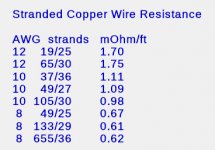
How much damping factor is enough? Consider that speaker wiring introduces resistance between the amplifier and the speakers and must be considered in the net damping factor equation.
If #10 speaker wires are 15 feet long (30 feet round trip), the the resistance will be around 30mOhms. That alone would result in a damping factor of 267, assuming R_int=0.
DF_amp = 8Ohms / R_int
R_net = R_int + R_wires
DF_net = 8Ohms / R_net
Below are some stranded copper wire resistances.R_net = R_int + R_wires
DF_net = 8Ohms / R_net
If #10 speaker wires are 15 feet long (30 feet round trip), the the resistance will be around 30mOhms. That alone would result in a damping factor of 267, assuming R_int=0.
Attachments
Is that the amplifier DF or the net DF? With 30' of #10 wires, if the amplifier DF=200, then the net DF is 114. It the net DF is 200 then the amplifier DF must be about 800.IME, 200 on 8 Ohm. But depends on the speakers.
For Open baffles for instance, a low DF is fine too.
Is that the amplifier DF or the net DF?
Amplifier DF.
BTW, I'm not sure that the cables raise the DF in the way you think. Mines are very thick, equal to AWG6 I think.
well , with perfect pair of pucks , I would need to invest my kidney and liver (both in great shape , tnx for asking) , to induce some 2nd
luckily , they aren't ideal , so some sweetness easier to get with trick or two ..... no need for miracles ....... even if this amp , as is , is on verge of Miracle
The only thing impossible about having NFETs and PFETs with the same transconductance is the internal capacitances. At very low frequencies the even harmonics would cancel, but at high frequencies even harmonics get seriously bad. The design issue is to choose the "right" balance of the transconductances.
The only thing impossible about having NFETs and PFETs with the same transconductance is the internal capacitances. At very low frequencies the even harmonics would cancel, but at high frequencies even harmonics get seriously bad. The design issue is to choose the "right" balance of the transconductances.
Can you quantify at what frequency the harmonics are a problem and what exactly "seriously bad" is?
I think that this is more than one conversation.
1. transistor matching. How close the transistors have to match to make a "good" amplifier? Which parameter is the most important? Second most important? ....etc.
2. How large of a population of transistors is required to produce some "good" matching pairs?
3. What is a "good" amplifier?
These are just a few off the top of my head. I am sure the community could create a concise list.
I have said this recently, it is a smart thing that PL buys hundreds of thousands of devices. Selecting matched pairs allows building simple amplifiers that measure well and sound good.
For the DIY builder, how much degradation happens using non-optimally matched pairs for each stage?
I think you would have to break it down by stage and it would be different for every different amplifier topology.
.
1. transistor matching. How close the transistors have to match to make a "good" amplifier? Which parameter is the most important? Second most important? ....etc.
You can simulate this
")
well , food for thoughts/brain .........
-DEFiSIT (as far as I know , soon to be SIT-3)
-several PL amps , having strategically placed CCS-es in specific OS quadrants , to brake symmetry
..... everything with goal to induce specific THD spectra , normally not possible when complete symmetry is in command
so , conclusion - full symmetry of output parts is just one of possible ways - we can search for it , or we can avoid it
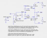
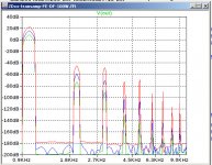
Yes, there are tricks to modify the harmonic character of the output stage itself. Without such tricks I see H2 about 18dB higher than H3 at 1kHz, 1W, 8R in the standalone output stage driven by a perfect front end with 1K output impedance. Below is the test circuit and the spectra for 1W, 5W, and 25W.
I have been running simulations where the FE is tuned to be as "neutral" as possible, i.e. so that the FE does does not introduce even harmonics, particularly via the feedback loop. This might help to reduce the variations of the output spectrum due to variations in the speaker load resistance. Work in progress.
I have been running simulations where the FE is tuned to be as "neutral" as possible, i.e. so that the FE does does not introduce even harmonics, particularly via the feedback loop. This might help to reduce the variations of the output spectrum due to variations in the speaker load resistance. Work in progress.
Attachments
old joke :
-what's easiest way to catch a Wabbit?
-put pinch of salt on his tail .......
it took me 2 decades to finally got a catch .....

it's good ..... I'm starting to see us , Greeddy Boyz, with Papa's eyes ..... and I can tell ya , it's more and more fun that way
spinning my head for several hours* , then relaxing at least half an hour , ROFL
*put every damn part value , in every damn iteration , under extensive battery of tests ...... practically everything I could think of ..... and that took me several months
life is good
-what's easiest way to catch a Wabbit?
-put pinch of salt on his tail .......
it took me 2 decades to finally got a catch .....
it's good ..... I'm starting to see us , Greeddy Boyz, with Papa's eyes ..... and I can tell ya , it's more and more fun that way
spinning my head for several hours* , then relaxing at least half an hour , ROFL
*put every damn part value , in every damn iteration , under extensive battery of tests ...... practically everything I could think of ..... and that took me several months
life is good
Last edited:
I have been running simulations where the FE is tuned to be as "neutral" as possible, i.e. so that the FE does does not introduce even harmonics, particularly via the feedback loop.
Usually my go-to approach. I find that the output stage is the best
(if not easiest) place to play with the symmetry.
That is good to know. I was beginning to infer that from many of your previous remarks.Usually my go-to approach. I find that the output stage is the best
(if not easiest) place to play with the symmetry.
What is your current feeling about the H2 vs. H3 level (at the output) in the zero degeneration amps where the higher order harmonics fall off very rapidly? At a mid-level power would you want H2 much larger than H3? Do you have a criterion about when it is necessary to "tune" H2/H3 of the OS?
- Home
- Amplifiers
- Pass Labs
- F4 Beast Builders