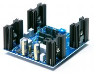
There have been some comments about the Zobel network shown in the 6Moons photos. I do not know what kind of speaker loads (or lack thereof) were causing problems without the Zobel.
Actually, it is not there to address a known problem. With most PL efforts
the output stage is sufficiently familiar that I dispense with the Zobel
because it has a history of being unnecessary. This output stage is a
bit different, as is the front end, so the Zobel simply adds a belt to the
suspenders in the design. It is possible that it will be deleted in the
future.
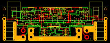
I got bored with simulations and I am procrastinating on modifying existing PCBs, so I spent the day doing a new PCB layout which implements the topology in post #1460. The board has dimensions 8.0" W x 2.625" H, which give the maximum area allowed for the PCB fab service I intend to use. The board is somewhat crowded as a result.
I intend to bench test the low feedback design by modifying one of my existing PCBs before fabricating this layout.
I intend to bench test the low feedback design by modifying one of my existing PCBs before fabricating this layout.
Attachments
Very nice artwork! Real Firstwatt, Papa's style.
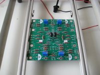
This is my version of the frontend, kind of UGS - Sony VFET pt2. Learning how to use Kicad finally pays off. I can configure this PCB in many ways to experiment. With or without degeneration of the small MOSFETs, EUVL trick for the JFET's or no degeneration at all. Balanced or left - right frontend.
Swiss army knife...
I will experiment with different output stages. But I think I will build this one Generg gave us first.
Did you actually build it? Instead of using many paralleled IRFP240's, using two hockey pucks will be nice to try.
Attachments
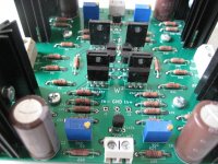
Attack of the Clone(r)s !!
An externally hosted image should be here but it was not working when we last tested it.


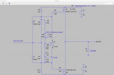
My next goal is to modify my (spare) ZD25 PCBs for good performance at global feedback levels of around 12 dB, rather than 40+ dB of my current build. In simulations for the circuit topology below, I have found some very good parameter sets:
I am very interested to learn how you find this variation in practice as it is very similar to what I am currently building. I can offer a small change that I think will improve this further: connect the cascode feedback resistors to either side of the bias spreader. I appreciate that this complicates your arrangement for adjustment with a single trimpot but I think you will find it improves the low frequency response by including the caps in the cascode connected feedback loop.
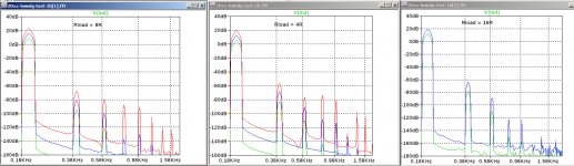
My optimism about the 12dB global feedback simulations was destroyed when I discovered that the harmonic spectra are highly dependent on the output load resistance (Rload). At a particular Rload I can adjust the FE to cancel H2, and the higher harmonics above H3 fall off quite rapidly. If I then change Rload, H2 and the harmonics about H3 get very bad unless I readjust the FE cancellation. I believe that the problem is the due to the transconductance mismatch of the OS FETs and can only be solved by either high levels of global feedback or better matching of the OS FET transconductances. I tried two difference approaches to FE H2 cancellation: 1) cascode feedback with unequal (adjustable) feedback resistors, and 2) identical cascode feedback resistors (or none) with unequal JFET load resistors using the capacitor DC degeneration trick.
The plots contains the spectra for Rload=8R, 4R, and 16R respectively, at 200Hz and 1W (green), 5W, and 25W. The spectra for $R and 16R may not look that bad until you see the numbers in the attached text file.
The plots contains the spectra for Rload=8R, 4R, and 16R respectively, at 200Hz and 1W (green), 5W, and 25W. The spectra for $R and 16R may not look that bad until you see the numbers in the attached text file.
Attachments
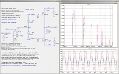
Here is a standalone LTSpice file for simulation a hocky-puck output stage using a "perfect" front-end, with variable open-loop gain (OLG) and closed-loop gain (CLG). Give it a try and experiment with various values for Rload, Watts, Fin, Vpwr, ...
Attachments
- Home
- Amplifiers
- Pass Labs
- F4 Beast Builders