Hello Brother, just so we are all on the same page here (I'm telepathic).
I am assuming the measurement of Vgs is taken between the Gate and Ground in both cases not between Gate and Source.
Gate and ground is the correct way as we are looking at the effect the source resistor has on the mosfet as it will be used in circuit.
We are assuming the resistor is now part of the mosfet (imagine it is inside the mosfet).
Last edited:
Because lhquam told us to study the speech of Nelson at BAF2016 more arduously..... ")
I did it again. A thing that I already remarked already some time ago, got my attention again.
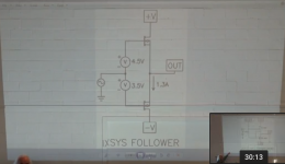
The Vgs values he shows for the P and N pucks at 1.3A and zero offset!
He has a fairly big difference between the Vgs values.
P channel 3.5V and N Channel 4.5V. That is a difference I never had with my parts. My difference was always much smaller around a half Volt. Look at my last picture some postings ago.
Is the big difference an expression of big difference in transconductance, so the N type needs much more Vgs to get the 1.3A, means lower transconductance?
But this difference could also be a result of a different Vgsthreshold maybe from 3-5V.
Hm,hm, hm.......
I did it again. A thing that I already remarked already some time ago, got my attention again.
The Vgs values he shows for the P and N pucks at 1.3A and zero offset!
He has a fairly big difference between the Vgs values.
P channel 3.5V and N Channel 4.5V. That is a difference I never had with my parts. My difference was always much smaller around a half Volt. Look at my last picture some postings ago.
Is the big difference an expression of big difference in transconductance, so the N type needs much more Vgs to get the 1.3A, means lower transconductance?
But this difference could also be a result of a different Vgsthreshold maybe from 3-5V.
Hm,hm, hm.......
Attachments
Don't forget Vgs threshold may also be different brother (Edit: you actually already said that. hahaha). So not necessarily indicating differences in tranconductance, but you could go hunting all the data sheets, to see what matches that.
I honestly wouldn't worry too much, just use whatever tricks you need to get the sound you want.
Edit: reading off Id of 1.3A from the data sheet won't be easy.
I honestly wouldn't worry too much, just use whatever tricks you need to get the sound you want.
Edit: reading off Id of 1.3A from the data sheet won't be easy.
Last edited:
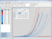
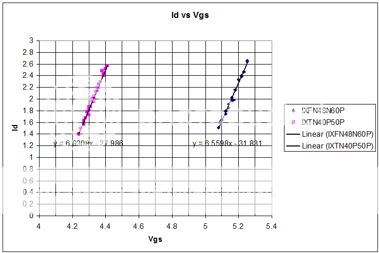
Indeed I looked at my fund of IXYS and I found some N parts that have this high Vgs at 1.3A. Look at the most right blue line. But you see most blue ones are more left.
It is the IXFK120N20, unfortunatly I owe only the K Version with TO-264, they were cheaper for thesting purposes.
So I suppose the IXFN120N20 with SOT-227 would have the same range, but how many I have to buy to get the one with the 4.5V? Could get expensive, and it is not secure if this is really the bill......
Attachments
Look at the capacitance characteristics. I am not sure how Nelson dealt with the gm issues. I am in the process of doing some extensive measurements of two of the IXYS FETs at about 1.3A-1.5A and 24V and will report my findings. Here is a teaser:
Attachments
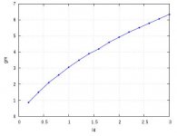
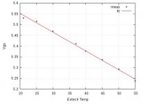
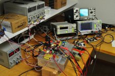
Nice work mate.Look at the capacitance characteristics. I am not sure how Nelson dealt with the gm issues. I am in the process of doing some extensive measurements of two of the IXYS FETs at about 1.3A-1.5A and 24V and will report my findings. Here is a teaser:
What part numbers are you working with at the moment?
Are you also planning on doing measurements at 2A?
I'll make a start after Christmas. Pretty busy with the family at the moment.
Last edited:
I am not sure how Nelson dealt with the gm issues.
Push pull takes care of most of it, but as far as I am concerned, this is the absolute beauty of it. Other people might want to micro manage it, but I like a wild beast, nothing to take care of here for me.
Last edited:
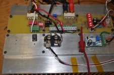
here some details about my N APT and P IXYS types.
N type is an old APT20M19JVR
P type an IXYS IXFN170N10
Interesting idea. Perhaps these could be used?

difficult to say...
data is here
APT50M50JVFR | Microsemi
it does not have the low capacities Papa shows for his IXYS in the BAF2016 talk.
It seems to have a fairly high transconductance so it will be difficult to find a P channel that is even higher.
But keep them, who knows....
I think that a real working beast will still last some weeks...knowledge and information coming in brains and from outside, if.....
Merry Christmas!
I promise I built it. Hahaha
The table!
- Home
- Amplifiers
- Pass Labs
- F4 Beast Builders