ezkcdude said:
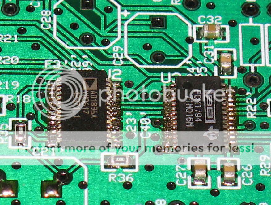
Note that he used an Abracon smt XO. It seems to have worse jitter specs than the Crystek part that I specified in the XO. However, I may not be comparing apples-to-apples. The crystek part specifies 12kHz-80MHz at 0.5 ps typical, 1 ps Max. The Abracon part gives period jitter at one sigma (1 std dev?) as +/- 25 ps Max. It's like they do this on purpose to make it difficult to compare parts.
Yes, he said he used a Crystek part in an earlier post and then realized it was actually the Abracon SMD
")
The Abracon you specify for the Ezdac seems to be very good, as me and Ray noted the better external regulator made a far greater improvement than swapping the Abracon for a more expensive Tent XO
The SMD Crystek I have is used in a different dac (Pedja AYA) and is 50mhz for the Asynchronous reclocker
Hi guys!
It's been a while... but nonetheless i've been busy !
!
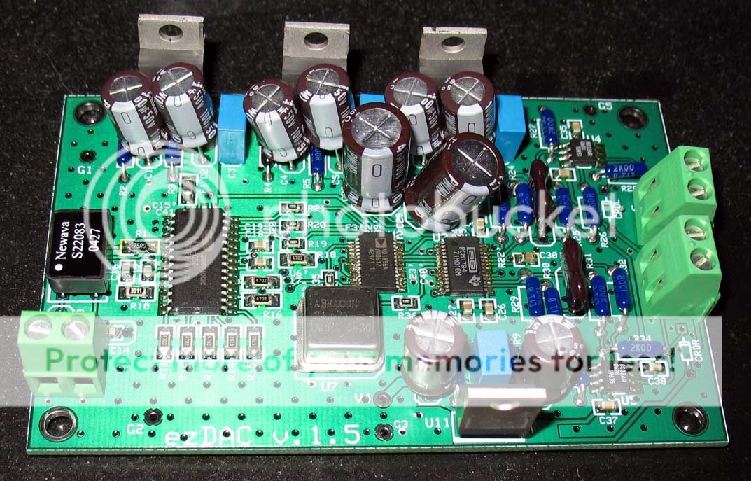
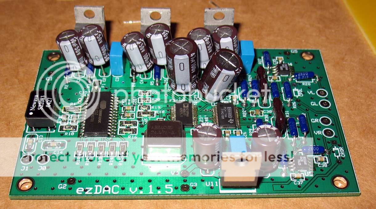
The v1.5 ezDAC is already singing for some time now, and my v1.5 pictues are finally finished.
So i've put them on-line! The page still needs some work and will be updated, but most of it is done now.
How's it going with the other v1.5 builders anyway? Any feedback yet?
Regards,
Ray
It's been a while... but nonetheless i've been busy
!The v1.5 ezDAC is already singing for some time now, and my v1.5 pictues are finally finished.
So i've put them on-line! The page still needs some work and will be updated, but most of it is done now.
How's it going with the other v1.5 builders anyway? Any feedback yet?
Regards,
Ray

Well, it still beats the cr@p out of my CD67 collection .
And a bit less cr@p out of my SA8400. The 8400 is still better in SACD playback, but the difference is not big!
I updated v1.5 with even better components: I used more BGs and bigger SMD decoupling caps. Where possible, I used C0G or NP0 caps. The lay-out of the v1.5 board has also been improved. All together, it sounds a bit more open and fluid than it already did, and it generates a very nice soundstage.
Regards,
Ray
.And a bit less cr@p out of my SA8400
. The 8400 is still better in SACD playback, but the difference is not big!I updated v1.5 with even better components: I used more BGs and bigger SMD decoupling caps. Where possible, I used C0G or NP0 caps. The lay-out of the v1.5 board has also been improved. All together, it sounds a bit more open and fluid than it already did, and it generates a very nice soundstage.
Regards,
Ray
Hey, Ray! Nice to see some life here. I haven't had time in months to work on the project, but I did recently order a stencil so I can try my hand at some toaster oven soldering for my next build. The spring semester is almost over here, so hopefully, over the summer I will be able to find a little bit of time to myself. Thanks, for posting more pictures and putting up your custom BOMs. Everything looks (and hopefully sounds) great.
A stencil should make things a lot easier. Is it expensive?
I read about the toaster method, it will probably work fine after some experimenting. I worked with a small infra-red oven once, and that was nothing more than two 500W halogen light tubes with a temperature controller. I hope you'll find some time soon, cause it's very bitter that you were not able to listen to your own project yet
This DAC is very worthwhile Simon! I use it for all my sources that have a digital-out. All i'm looking for now is a nice S/P-dif switch
Regards,
Ray
6h5c said:A stencil should make things a lot easier. Is it expensive?
I read about the toaster method, it will probably work fine after some experimenting. I worked with a small infra-red oven once, and that was nothing more than two 500W halogen light tubes with a temperature controller. I hope you'll find some time soon, cause it's very bitter that you were not able to listen to your own project yet
This DAC is very worthwhile Simon! I use it for all my sources that have a digital-out. All i'm looking for now is a nice S/P-dif switch
Regards,
Ray
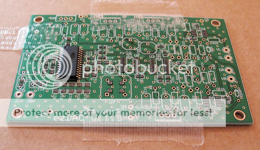
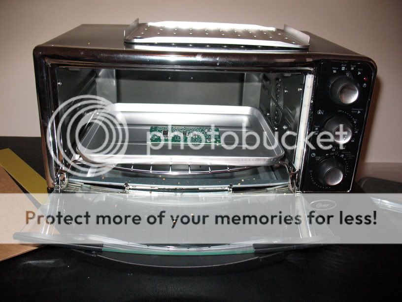
Ray, I actually just finished my first toaster oven board. Well, most of it anyway. I didn't have the 75R for the input, but I was too impatient to wait. It's pretty neat. I won't know if it worked until I solder the other components, which I am not sure when I will get around to it. As for the stencil - it was $99 USD. Not too bad, and it worked very well for putting on the solder paste. Actually, that part was easier than I thought it would be. I learned that you should wait about 10 minutes before trying to place the components, because the paste becomes a little bit tackier. Otherwise, the 0805 can be sort of difficult. Once I got it going, the process of placing components was a breeze. Then, I put it in the toaster (Oster convection oven that I saw recommended on a website), and turned up the heat to about 350F (175C) and waited a few minutes. I checked the paste and it was still "wet", so I turned up the heat to 425F (225C) and waited a few more minutes. Then, after waiting a minute or two, all of sudden I could see the paste starting to get shiny on each of the pads - within 10 seconds all the pads were shiny and "bubbling", so I turned off the toaster. I'm now waiting for it to cool. I'm going to post a series of pics. Stay tuned...
Here are some pics:
Board with solder paste before oven treatment
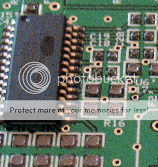
Closeup
Board in toaster oven
Board comes out of oven
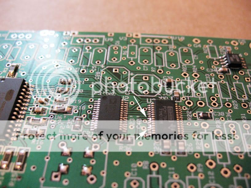
As can be seen there are some solder bridges - quite a few actually. I am going to try to remove them with solder wick now in the normal way.
Overall, though, this was a good experience. It appears applying the paste and placing the components are not too difficult. In addition, using the oven surprisingly easy - I don't really see a need for complicated temperature profiles. So far, the solder bridges are a little annoying - but should be easy to take care of. Also, clean up of the stencil and "solder squeege" may be a pain. I think I can soak them in alcohol.
Board with solder paste before oven treatment
Closeup
Board in toaster oven
Board comes out of oven
As can be seen there are some solder bridges - quite a few actually. I am going to try to remove them with solder wick now in the normal way.
Overall, though, this was a good experience. It appears applying the paste and placing the components are not too difficult. In addition, using the oven surprisingly easy - I don't really see a need for complicated temperature profiles. So far, the solder bridges are a little annoying - but should be easy to take care of. Also, clean up of the stencil and "solder squeege" may be a pain. I think I can soak them in alcohol.
Re: next pcb
I still have a handful left.
tomperr said:Ezkcdude are you going to order knew pcb or maybe you have them?
I need 1 or 2.
Regards Tom
I still have a handful left.
mnrbig said:Hi All
Sorry for going over old posts, but I did notice that this DAC was used by ezkcdude on his squeezebox. How does it compare with the Squeezebox built in DAC as this is also Burr Brown.
I've never switched back to the Squeezebox DAC, if that answers your question.
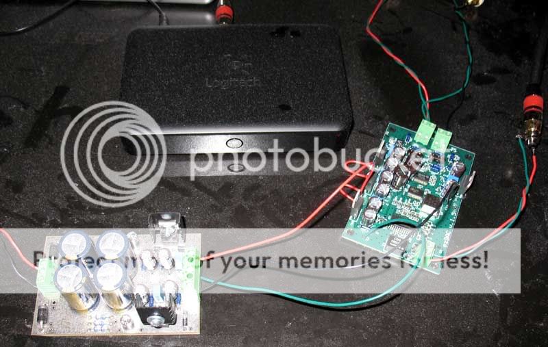
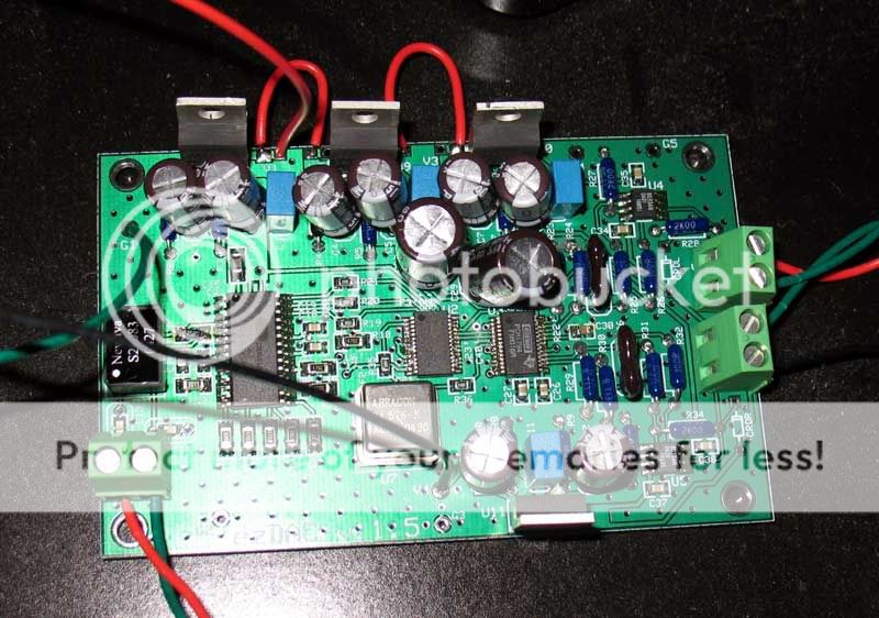
Ray, the music is playing!!! I'm glad people kept working on the project, as I got re-inspired to commit to building another one for myself. I'm also glad the toaster oven technique turned out to be so useful. I'll certainly use it again. So far, the DAC sounds great. Here are some pics. Now, I got to case it up...Stay tuned.
ezDAC v.1.5 with ezDual and SqueezeBox Duet Receiver
ezDAC v.1.5 with ezDual and SqueezeBox Duet Receiver
Looks good
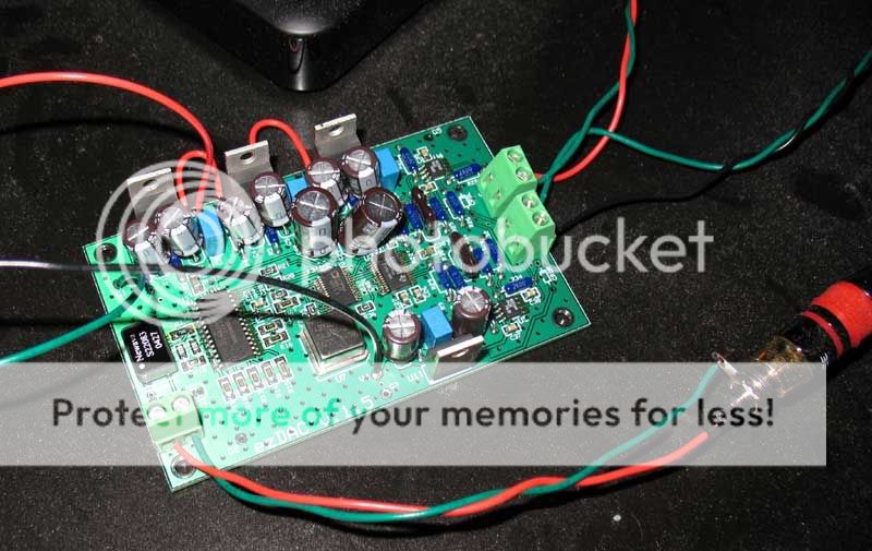
I've started on mine recently, it will be fitted into a Marantz CD17KI I have bought for this very project. I will be setting it up using the I2S bus.
All components are soldered using silver loaded solder and the large caps are 220uF BG FK (16V & 25V).
It's a slow project as i'm fitting it in between my normal work.
Here are two pics of the pcb in its current state
PIC1 PIC2
Brent
rowemeister said:Looks good
I've started on mine recently, it will be fitted into a Marantz CD17KI I have bought for this very project. I will be setting it up using the I2S bus.
All components are soldered using silver loaded solder and the large caps are 220uF BG FK (16V & 25V).
It's a slow project as i'm fitting it in between my normal work.
Here are two pics of the pcb in its current state
PIC1 PIC2
Brent
Looks even better in the flesh, can't wait to hear this!!
- Status
- This old topic is closed. If you want to reopen this topic, contact a moderator using the "Report Post" button.
- Home
- Source & Line
- Digital Source
- EZDAC is singing now!!!