EZdump2 latch-up
Hey guyz, I simulated minek123's latest file and found that at an input overdrive of 1.3V or more, the circuit latches up to +40VDC. It seems that there is not enough positive feedback for the amount of bootstrap so the problem goes away if you increase R9 or R15. Seems like R9 could be 470 or R15 could be 33k to be safe.
I suspect I may find other things to say about this amp but I'll leave it to another post.
BTW, get well soon LV, DIYA needs you.
Attachments
The On-semi (and minek123) model for MJ21194 is seriously messed up. It saz the beta is BF=10000, but there must be more errors because fixing that parameter results in other problems. However the model for MJL21194, the plastic package version is fine. I suggest just using the MJL model.
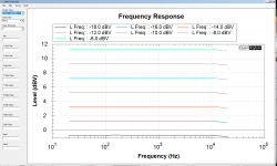
Decrease the positive feedback R14 to 39k or more. See modified circuit for loop response.Any suggestions how this corrected?
Attachments
Hi Elvee, good to see you back in business! Hope you are doing better!
If you have a moment, could you please have a look at post #131 in this thread?
https://www.diyaudio.com/forums/solid-state/263065-ez-dump-dump-current-trying-14.html#post6318979
I haven't tried any fixes yet to get rid of this oscillation..
I guess most likely I need to adjust the value of one of small compensations caps..
Thanks!
I haven't a clue: I remember that the circuit was rather touchy, and would generate the kind of artefact you see when improperly stabilized, but in the end I got it reasonably stable.
I'll have a second look at my prototype one of these days.
Note that the parasitic capacitances from the bootstrapped section to the rest of the world play an important role, and some effects can be couter-intuitive: there are places where adding a stopper resistor or a compensation cap can have the opposite effect
Both are plausible, but C8 R19 imply something related to the GNFB, and most of the stability issues I encountered were just a second stage affair.
You can test the second stage in isolation by removing U2 and injecting the signal on the output pin.
The source has to be low impedance, 50 ohm for example or a short if you want to test the static stability. Don't leave this node open!
You can try to tweak R10 R26 (and C9 C10) in the real world; they certainly have some kind of influence
I'm trying now to make my model work with actual transistors I used.
So far it doesn't work at all in spice; my actual build at least worked to some degree.
ASC attached.
One the problems - idle current for output devices is way too high.
This does not correspond to the actual build..
So far it doesn't work at all in spice; my actual build at least worked to some degree.
ASC attached.
One the problems - idle current for output devices is way too high.
This does not correspond to the actual build..
Attachments
Last edited:
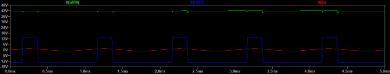
In sim, the circuit is latched-up because with the 45V rails, the CM range of the second stage is exceeded (it is limited by the 30V supply zener).
As a result, the output is stuck to the - rail.
As a quick fix (more a theoretical proof in fact), I changed the 30V diode for a 51V one, and it seems to behave more normally.
In reality, 51V would be too much for most opamps; a more reasonable solution for high voltages would be the recalculation of the FB resistors ratio for the second stage, to remain within the 30V limit.
PS: I made a little room in my inbox, if you need to send me a message
Attachments
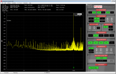
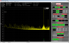
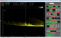
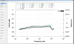
Here are some measurements of my active current dump amp build,
done with qa401 audio analyzer.
Thd from 0.037% at 3W to 0.049 at 50W.
Obviously they slightly differ from the sim (unfortunately for the worse).
done with qa401 audio analyzer.
Thd from 0.037% at 3W to 0.049 at 50W.
Obviously they slightly differ from the sim (unfortunately for the worse).
Attachments

Last edited:
It is instructive, but puzzling: one would think that the large loop gain provided by the opamps would annihilate the distortion, but it doesn't.
The bridge balance must be good, otherwise the low-level THD would climb.
I remember trying to measure the THD of another composite amplifier (not a current-dumping one), but I didn't succeed, even with combined filtering-subtraction methods: it was below the ppm
The bridge balance must be good, otherwise the low-level THD would climb.
I remember trying to measure the THD of another composite amplifier (not a current-dumping one), but I didn't succeed, even with combined filtering-subtraction methods: it was below the ppm
- Home
- Amplifiers
- Solid State
- EZ-Dump: dump your current without really trying