Thanks!
Same concept was used for Elvee's Circlophone build (2 of them):
http://www.slowbears.com/flickr/Circlophone/
Same concept was used for Elvee's Circlophone build (2 of them):
http://www.slowbears.com/flickr/Circlophone/
@Minek123
Wow!
This is not a amp....This is a piece of ART!
Bravo!
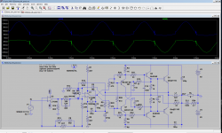
The spikes are caused by the unbypassed R22, R23: the + and - paths are allowed some independence, but when they meet again in C1, the discrepancy causes a conflict which is resolved by the (harmless) current spikes.I'm getting ugly spikes in Q3/Q4 current..
Passive ver. 1
Final results are good, as far as I can tell, but original amp
didn't have these spikes...
Looks like they are caused by R10/C9.
Increasing R10/R26 to 100Ohm removes spikes, and lowers THD (at least at 1kHz).
A 100nF across the bases of Q3 and Q4 eliminates the effect (and has no detrimental effect, I just tested it on the prototype)
Not really 'compulsive', more like 'serial'Sounds like a good plan for a compulsive builder!
")
It takes me months to select/decide which amp to build, and I prefer
to select something different, unusual.
Alpha Nirvana is not really 'unusual', but I've never built A class amp,
so I want to check for myself if they really sound good..
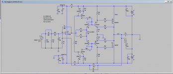
One of the next ones might be this one (attached)...
Attachments
Hi minek123,Not really 'compulsive', more like 'serial'
It takes me months to select/decide which amp to build, and I prefer
to select something different, unusual.
Alpha Nirvana is not really 'unusual', but I've never built A class amp,
so I want to check for myself if they really sound good..
One of the next ones might be this one (attached)...
You made my day!
My with corrections is here AUDIO_EW-WW_Hegglun_Square-Law-Rules_Sep-1995_errata.pdf - Google Drive
Most of my articles (apart from Linear Audio) are here IansArticles - Google Drive
(use List View for a compact list. Feel free to Downoad All for reading).
"Unusual" features are Common Source (CS) output stage with no source resistors for high idle current and wider Class-A region. Why CS? Followers were used in original power amps when the FT of the power transistors were abysmal. Now with fast power transistors you can use CS. Also with followers using L or D MOSFET their high threshold voltage reduces the output swing, but using CS this is overcome. No need for extra rails to get the full output swing.
The original used laterals and did not need thermal coupling of Q1,Q6 to the heatsink. But using DMOS will require thermal coupling of Q1,Q6 to the heatsink. Also with DMOS don't forget zeners across gate-source (the Hitachi laterals have them built in). Thses zeners can also provide current limiting for SOA, eg 6v2 for the n-ch and 6v8 for the p-ch).
I also ran R25,R26 from the zeners without CCSs. KISS.
Also I have since moved away from using capacitor C6 across the feedback resistor to minimise the effect of RF from the speaker leads.
And for capacitive loads you do need an output inductor and damping resistor.
It did sound good. I built one for an audiophile friend, who compared it to a his Williamson (UL version), and he like it. His speakers were really old Midax? horns with 18 inch woofers in a huge cabinets - I think they were 105dB/W/m and they sounded great on his Williamson.
Cheers,
Thanks Ian! When I start this build, I guess I'll also start a new thread for this.You made my day!
It sims very well even with hexfets.
I retested on my prototype: it works equally well with or without the additional cap.100nF added...
In the sim, if the current in the class A amplifier is increased (by removing R26 for example), it eliminates the effect.
This can only increase the quality, but at the cost of a higher quiescent dissipation
Attachments
They improved the coupling of the opamp to the diamond buffer: their "stiffness" guaranteed an always maximum gain, and prevented non-linearity in the input current from being translated into a (tiny) distortion voltage.
It is thus normal to see a distortion increase without them, but in sim at such low levels, the change is indicative.
The actual value will depend on many other factors.
I had to remove them for this version to allow the 470 ohm resistors to play the role of base-stoppers.
The multiple bootstraps are very demanding for stability, and something's got to give somewhere
It's a difficult one: sim and reality seem to disagree, and logically the reality should prevail, but my build uses BD139/140, etc. so it is not impossible that other devices/layout/etc. cause problems.
The bootstrap has many advantages, and not only for ratings and dissipation but also for performance: it improves linearity.
Unfortunately, it can cause weird and difficult stability issues as well.
If possible, I'd recommend to include both options in your PCB: if version 1 proves too difficult, you can always fall back to ver 2, which is inherently more placid
Yes, that was one of the compelling reasons that drove me to bootstrap these transistors.Elvee, if buffers are connected to rails, they gonna run hotter (1W each).
Unfortunately, we are left with a practically binary choice for the collectors location: rails or bootstrap. Other solutions could be conjured, but they are even less attractive, or more problematic (if someone has a lightbulb moment about that, he/she would be welcomed as a messiah!).
Yes, more than ever, and the drivers too.Should they still thermally track output devices, like you suggested before, for TO-92 devices?
That's unfortunate for a CD amp, where thermal issues shouldn't matter, but realistically it would be unwise to dispense with it
Oh no! Tracking is even more important, unless you leave the CD topology do real heavy-lifting (which is not advisable, because the CD theory neglects higher order effects, and the accuracy of the bridge components is not perfect either)Since they gonna run hot, I guess tracking would be pointless in this case...
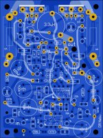
I'll proceed with a new build for passive version 1.
New pcb in progress...
6 x 8 cm, same size as 1st version.
1st version is still my regular amp, being used every day, for several months now.
Working perfectly without any problems.
As it runs very cool, this next version will be passively cooled; no need for fans.
Elvee, the 1st version was showing small oscillations (5MHz) with LT1056. After switching to LF356, it worked perfectly.
Do you think this new, passive version should behave better with LT1056? I guess we will see..
Attachments
Last edited:
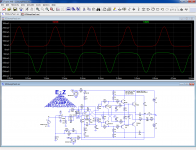
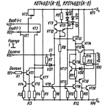
Elvee, I found one interesting amplifier, published in Russian Radio magazine in 1987.
It seems to use floating op-amps as far as I can tell, using simple Zeners, and ground referenced to the output.
Output devices also looks interesting (non-switching?).
There are certain similarities to your design.
The op-amp is Russian equivalent of Fairchild UA740.
What is your opinion about it?
I'm waiting for new boards for the passive version of current dump amp, they should arrive very soon.
Attachments
Last edited:
Interesting: it uses a diamond driver, and no OP degeneration resistors, something I found possible too (I have built and described a buffer stage based on that principle), to my surprise..
There has to be something peculiar with this combination, because the first thing it should do is go into thermal runaway, -but for some reason, it doesn't-.
The floating opamp is very much in M. Tillotson's style, but it doesn't seem to have provisions to drive the OP's close to the rails at VLF.
I don't think the opamp is the equivalent of a µA740: it has an explicit GND connection, something rather rare with opamps (I think some European types have such a connection).
Unlike EZdump, it has no additional buffering layer between the opamp and the driver, which certainly eases stability issues ( Mark also used that method and seemed to have an easier job of making the thing stable)
The drawback is that with weak opamps, the OP power is going to be limited, but in this case, the power looks relatively modest, thus it shouldn't be an issue.
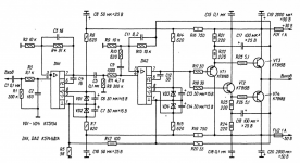
closer look
Both Op-amps float somewhat and the second one has an RC across the inputs to reduce the OLG. Years ago I used that approach to stabilize a LM377 for unity gain.
With the diamond OP, it is limited to 16 Ohms, maybe 8 Ohms at reduced voltage. It would drive a lot more current if they had cross coupled the diamond.
It helps to download the schematic and crop it.
Attachments
Last edited:
- Home
- Amplifiers
- Solid State
- EZ-Dump: dump your current without really trying