Jay_WJ said:My notch filter is at 975 Hz.
Well that changes everything. I assumed you used the notch for a higher rolloff of the woofer, in an elliptic filter sort of way, with tuning frequency somewhere above 1200Hz. It could cause a peak at the knee above the NOMINAL SPL level because of the resonance. If it's high enough it WILL cause ringing. In fact any high Q ratio of the L and C values can do this. I don't know how bad and I'm not going to debate the point either. Get a book on filter theory. (if you find a good one let me know
 )
)OTOH with it tuned at 975Hz it isn't really a high Q peak at the knee I don't *think*. Because it's just returning to the NOMINAL SPL level that it would be if the notch wasn't there. Know what I mean? Although it could effect group delay I think...of course the magnitude of the peak is what determines how bad this is. Zaph's is what, one pixel? And yours looks like a solid 1.5db? I'm trying to find info on this very topic of filter Q, so this is just my understanding so far. Anyway it was just a friendly suggestion and I don't feel like getting into a right/wrong argument.
I don't feel like getting into a right/wrong argument, either
Just want to make sure I'm doing okay with this design.
I still think what is important is the acoustic response. All kinds of tricks and filters in a crossover are all used to obtain a target acoustic response, including a target roll off with intended Q, for a driver, aren't they? A transfer function, no matter how messy it is, simply shows the network's output to a flat input.
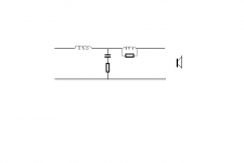
I have used a "notch" on my bass (3way)
After reading that a notch introduce ressonance, I tried to do like Zaph and removed the resistor, but I didnt like it
Then I tried to remove the cap and it proved much better
I ended up with simply a coil and a big resistor(39ohm), much like its often done to make BSC
It is very clear that some high frequency ringing has disappeared and sound is now much nicer, soft and smooth
Offcourse its not in general and must be system related, and in this case its a notch that works outside the passband of a bass
I think its remarkable that a notch on a woofer can cause high frequency ringing in the whole system
Thanks !
I have to say that the coil and resistor is placed AFTER a "traditional" 12db filter (series coil and paralel RC)
And my finding may be influenced by flawed woofers, or other things
But I am quite certain that filter Q values are VERY important and have huge influence on transient response - someone has mentioned it to be more important than smooth FR response
Coming in late..
I might be coming into this conversation a bit late, and I haven't read everything posted, however I was wondering if anybody had thought about the old Heil air motion transformer tweeters for frequency response. As far as I remember, they were good down to about 950Hz. Aside from that, they are very, very good units, probably some of the fastest, most detailed things you'll ever hear (my opinion anyway)
I might be coming into this conversation a bit late, and I haven't read everything posted, however I was wondering if anybody had thought about the old Heil air motion transformer tweeters for frequency response. As far as I remember, they were good down to about 950Hz. Aside from that, they are very, very good units, probably some of the fastest, most detailed things you'll ever hear (my opinion anyway)
tinitus,
A bottomless LC notch filter always causes a maximal amount of ringing (or a bump as I called) right next to the intended notch frequency. So care is needed in using this circuit. When used in a frequency range where a woofer's response is rolling off for a target slope, the notch frequency should be high enough so that the roll off due to a series inductor can suppress the ringing at least by 30 dB down from the speaker's reference SPL. This is why an LC notch is used with a metal cone whose breakups are located at a high frequency. In this case, the larger the capacitor of LC is, the better the situation is. The reason is that a large capacitor also contributes to a faster roll off. This is why a metal cone with an LC notch is not appropriate for LR2 design, but for a higher order filter.
So, it all depends on HOw it is used. I think your intended filter slope were shallow (because you ended up with a series inductor and a big parallel resistor). This indicates that the capacitor in your LC notch was not that large. In this case, the bump caused by the filter should be audible.
There is nothing wrong with using a knee in the transfer function of the filter to correct the acoustical response. It will store energy, otherwise you couldn't get a knee. Look at the final CSD of the system to confirm that it isn't a problem.
Also... before you do too much work on a single FR curve make sure your measurements are really reflective of what is going on. I don't think it is a good idea to try to correct 100% for baffle diffraction effects. They change off-axis so you have to pick & choose how much you want to try to compensate on-axis. If you correct for them in one measurement you are going to get a bump in the other. Its just one of those design choices you make.
In terms of which tweeter I'd choose. They are all good but I'd stick with the Seas or the Peerless. They have a better reputation for consistency and that is very high on my priority list. I've built systems with both the Peerless and the Seas and you won't go wrong with either. Pick the one that appeals to you from a cosmetic standpoint and by cost and go build a speaker.
Nice, ... or could it be because my LC was a paralel notch (in series with the signal) ?
I have been told that all drivers has a dip around 1khz, fore some reason - some drivers dont show this dip .... it may have been smoothed in measurements ?
I think Troels has said that its nothing to worry about - maybe there will be artefacts from dealing with it, that are worse than letting it be ?
I have been told that all drivers has a dip around 1khz, fore some reason - some drivers dont show this dip .... it may have been smoothed in measurements ?
I think Troels has said that its nothing to worry about - maybe there will be artefacts from dealing with it, that are worse than letting it be ? [/B]
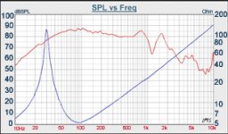
I know many midwoofers have a mlid dip around 1 kHz, and can be camouflaged a bit by a usual diffraction bump. But the 8945P's known dip is more severe and shifted from the center of diffraction bump.
Kevin Haskins said:There is nothing wrong with using a knee in the transfer function of the filter to correct the acoustical response. It will store energy, otherwise you couldn't get a knee. Look at the final CSD of the system to confirm that it isn't a problem.
Also... before you do too much work on a single FR curve make sure your measurements are really reflective of what is going on. I don't think it is a good idea to try to correct 100% for baffle diffraction effects. They change off-axis so you have to pick & choose how much you want to try to compensate on-axis. If you correct for them in one measurement you are going to get a bump in the other. Its just one of those design choices you make.
A good suggestion. In the PE measurement, the dip indeed becomes less deep at the 30 degree off axis. But it's still there. That's why I didn't go too wild in making the "knee."
tinitus said:Nice, ... or could it be because my LC was a paralel notch (in series with the signal) ?
Oh, I misunderstood that you used a serial notch. But what I said about the use of LC notch filter still holds. But the role of capacitor in the LC does no longer applies in your case. Anyway, basically you ended up with a sort of electrical 3rd order-ish topology (not exactly 3rd order because you used a resistor in parallel with a coil). Right?
BTW, a very interesting way of using an LC notch filter is using it to achieve a steep slope filter. In the case of serial notch filter (just the case you tried before), we can add a shunt capacitor to look like an electrical 4th order filter. This removes the notch filter ringing and makes a very steep filter. In the case of a parallel notch, we can add a series inductor to make it like an electrical 3rd order filter. This also suppresses ringing to achieve a steep roll off.
Most 6.5" & 7" drivers have a dip around 1.2k. It varies both in magnitude and location but it is there on about everyone of these drivers if you take enough measurements.
I've tried to determine why this is so. Mainly because one of the transducers I was involved in designing had a nasty suckout at 1.2K, otherwise it was wonderful. I tried adding damping at the cone termination via another glue joint on the front of the surround, I tried a different termination at the former (this design didn't have a dust cap) and I tried to determine if it was an issue with the cone, and a destructive interference set-up by the combination of factors. In the end I couldn't remove it or substantially alter it by changing the soft parts. This leads me to believe it is a diffraction related issue with the diffraction occuring at the surround, rather than the edge of the cabinet. Transducers being round is a rather unfortunate shape for minimizing baffle-like diffraction characteristics. ;-) But this effect does seem to correspond most with loudspeakers that have the largest surrounds. The frequency is related to the physical size of the loudspeaker (most surrounds for 6.5" drivers is about 5"). Five inches corresponds to a wavelength @ 2.6k and half that number and you have a relationship to our average suckout range.
Just a guess at this point but I'm looking into it further.
Kevin Haskins said:Most 6.5" & 7" drivers have a dip around 1.2k. It varies both in magnitude and location but it is there on about everyone of these drivers if you take enough measurements.
Yes, you're right. Zaph's 6.5 inch test shows that. Very interesting. Look here:
http://www.zaphaudio.com/6.5test/fr.html
With only a few exceptions, almost every 6.5 to 7 inch driver has a combination of a dip and a following uphill between 800 Hz and 2 kHz. A dip ranges from near non-existent to very deep, but a rise almost always follows it.

Its also the range where you start to see the cone going from a purely pistonic type motion into a break-up mode based output. The rule of thumb is when the effective diameter of the transducer (5") reaches half that wavelength then the cone starts entering the non-piston range. As a result the FR above this range has more irregularity than below.
The dip at 6.5K on the Peerless part is probably related to the dome diameter and its transition to the surround. It falls off to insignificance off-axis more than about 5-10 degrees. It falls into the category of something that is better off left alone. Design the crossover with the 5-10 off-axis data for better overall results. In that range it is perfectly flat (+/- 1db)
- Status
- This old topic is closed. If you want to reopen this topic, contact a moderator using the "Report Post" button.
- Home
- Loudspeakers
- Multi-Way
- Extremely difficult: Tweeter with best low-end performance...Please help!