analog_sa said:
I am more inclined to think people are scared off by unpredictable sonic performance.
Nonsense. Only these circuits are not that well known and did not become "popular". For me, there is no worse sounding amplifier than the ZEN (I do not count seventies class B nasty designs)
Just this week i noticed someone who spent loads of cash on Magnatec power devices and an outdated Elektor design that some considered predictable and questionable +2 decades ago.
Same week, a bloke from Romania spent a fortune on a 300Watt Patrick Turner modified Tilbrook MOSFET design, also slow mode stuff from the early 80s.
(Both in the solid state pics thread)
Seems that a lot of people are not scared to invest in real antiques.
Same week, a bloke from Romania spent a fortune on a 300Watt Patrick Turner modified Tilbrook MOSFET design, also slow mode stuff from the early 80s.
(Both in the solid state pics thread)
Seems that a lot of people are not scared to invest in real antiques.
analog_sa said:
I am more inclined to think people are scared off by unpredictable sonic performance. If one is prepared to invest into heatsinks, PS and metalwork a Krell or a Pass clone guarantees some level of sonic bliss.
This statement is close to what I'd consider a fact.
If you take a look at which designs have become popular, you will see that it's mostly designs that have been following a paticular route for a decade or more. People know what to expect, have seen the amps at other peoples places, and knows that there are loads of amps made by this particular designer out there....working amps that is.
Besides that, it brings confidence in to a design, if it's made by one of the known designers. I bet you that if Curl made a series of DIY projects, they would also gain enormeous momentum in a matter of weeks.
When Pass releases a new project, it's getting like 1000 hits within hours....not due to the project, but simply cause it's signed by "Pass".
Contrary to that, Sander, well he is.....Sander. You know him, I know him, and perhaps another 25 people on here have taken the time to take a look at his designs and try building it.
Magura
Magura said:Besides that, it brings confidence in to a design, if it's made by one of the known designers.
Duhh,
known
Jacco,
I wholeheartedly agree, especially since the majority of these transistors are used for building current sources and current mirrors and even a discrete DC protection. Add to that the fact that this is a bridged amplifier, in order to get sufficient output power in class-A without needing ridiculously large heatsinks, and anybody that has given the schematic a 2nd look will realize it is in fact not using that many transistors at all.
But here's the real question: since when is transistor count, or parts count for that matter, of a design a benchmark for the quality of a design, or its sonic performance?
Best regards,
Sander Sassen
http://www.hardwareanalysis.com
It's a real shame that designs as Bruno/Sander's ExtremeA and the ones by Glenn Kleinschmidt receive so little attention because people are scared off by a few dozen 5 cent small signal transistors.
I wholeheartedly agree, especially since the majority of these transistors are used for building current sources and current mirrors and even a discrete DC protection. Add to that the fact that this is a bridged amplifier, in order to get sufficient output power in class-A without needing ridiculously large heatsinks, and anybody that has given the schematic a 2nd look will realize it is in fact not using that many transistors at all.
But here's the real question: since when is transistor count, or parts count for that matter, of a design a benchmark for the quality of a design, or its sonic performance?
Best regards,
Sander Sassen
http://www.hardwareanalysis.com
PMA said:Sander,
would you be willing to display time domain responses, like 10kHz square, 1dB under full output voltage swing, into different loads, including speaker simulated complex load?
Thanks,
Pavel
It would complete the set of your measurements shown.
I'd be happy to provide further measurements but I don't have a ExtremA built up I can use for such measurements. I built two for myself that I sold after someone came over to listen to the amplifiers and made an offer I couldn't refuse. The prototypes have already been disassembled and the parts used for other prototypes and I haven't had time to build new amplifiers.
Best regards,
Sander Sassen
http://www.hardwareanalysis.com
Best regards,
Sander Sassen
http://www.hardwareanalysis.com
Pass or Krell? Hmmm, people tend to act as a herd because in our evolutionary history this has been beneficial.  There is also a matter of cognition as pointed out because there will be costs (monetary or time consumption) associated with search for something different.
In investment situations not following the herd can be very rewarding. I believe this can even be the case when building amps.
People act from what they believe is true and this is sometimes restricting their possibilities to find "the truth".
I find it refreshing and encouraging that a schematic like this is published here and that PCB are offered to members, thanks a lot
Sander.
It´s not much of a problem really, those who want to go the safe way, stick to Krell or Pass clones.
How does an amp sound? That's a hard question to answer. It depends a lot of the conditions that are around it. For the first time in 17 years a neighbor complained about my loud listening level ( usually I only play loud for some hours Friday or Saturday evening but now it sounded a bit "to good", tempting me to excess). She asked if I had bought new "bass amplifiers" and I answered "no but I do some experiments". In fact I have continued to work with room tuning and this ( to me made) the bass sound more "forceful" , agile ; made my perception of rhythms different and unfortunately may have gone trough the floor/walls in a more offencive way.
At the age of 57 I´m still surprised how much difference relatively
cheap and easily executed tweaks can offer. For sure some money are spent and time consuming it is. Easy when speakers will weigh like a small car if they ever get finished?
We are indeed dealing with systems and the outcome is sometimes predictable but far from always.
As a fly fisherman do I always want to catch a lot of fish? No that would probably be boring.
Oh well, this really looks like a very good amp. By coincidence, I'm a fan of bridged class A (for its lack of GND and PSU load signal currents) as well as that "constant voltage drop across Re"-autobias feedback loop, as I plan to design a somewhat similar amp concept currently (simming stage, so far, see my crude&silly aproach here (and in some follow-ups).
WRT to the ExtremA's schematic, isn't there one very important live saver connection missing in the output stage?
- Klaus
WRT to the ExtremA's schematic, isn't there one very important live saver connection missing in the output stage?
- Klaus
Klaus,
As I've personally drawn these schematics and many amps have been built from them, to the exacting performance figures as published, I'm afraid I'm at a loss what that connection might be?
Cheers,
Sander Sassen
http://www.hardwareanalysis.com
WRT to the ExtremA's schematic, isn't there one very important live saver connection missing in the output stage?
As I've personally drawn these schematics and many amps have been built from them, to the exacting performance figures as published, I'm afraid I'm at a loss what that connection might be?
Cheers,
Sander Sassen
http://www.hardwareanalysis.com
Hi Sanders,
I meant a connection from the output to the tap in between the diodes, so the overcurrent protection senses the individual drop across the Re's, not only total drop. I simmed it, not the same trannys but comparable ones, and I found short circuit currents to skyrocket without that connection -- would blow the fuses. Couldn't see any degradation in open-loop THD with the wire, also no change in the clamping action when one of the currents goes opposite polarity. So I assume that connection would be "legal".
EDIT: could be fine tuned with a series R (~47R) instead of the wire to allow more or less of class-B mode operation during high current peaks. Was that class-B "fallback" region a consideration?
- Klaus
Klaus,
The only condition where I can see this be a problem is when the amplifier is fed with DC rather than AC, otherwise the overcurrent protection is just working as intended. However if you set the bias current higher, the maximum peak current will be higher as well, which can result in the fuses being tripped prior to the overcurrent protection engaging.
No, class-B was never a consideration, it merely works in class-B when pushed beyond the class-A limits because another mechanism kicks in, which is partly due to the fact that the first stage has more output swing than the output stage itself. THD will see a (very) substantial rise when the amp is pushed into class-B operation.
Cheers,
Sander Sassen
http://www.hardwareanalysis.com
I meant a connection from the output to the tap in between the diodes, so the overcurrent protection senses the individual drop across the Re's, not only total drop. I simmed it, not the same trannys but comparable ones, and I found short circuit currents to skyrocket without that connection -- would blow the fuses.
The only condition where I can see this be a problem is when the amplifier is fed with DC rather than AC, otherwise the overcurrent protection is just working as intended. However if you set the bias current higher, the maximum peak current will be higher as well, which can result in the fuses being tripped prior to the overcurrent protection engaging.
EDIT: could be fine tuned with a series R (~47R) instead of the wire to allow more or less of class-B mode operation during high current peaks. Was that class-B "fallback" region a consideration?
No, class-B was never a consideration, it merely works in class-B when pushed beyond the class-A limits because another mechanism kicks in, which is partly due to the fact that the first stage has more output swing than the output stage itself. THD will see a (very) substantial rise when the amp is pushed into class-B operation.
Cheers,
Sander Sassen
http://www.hardwareanalysis.com
Thanks for the explanations, Sander.
I now found out that it was a simming error, I didn't do the full bridge ashamed: lazy guy that I am) and just set RL to half its value, connected to GND.
Now, as a full bridge, everything works as described (still I have to look why it doesn't in non-bridged mode), so forget about my objection. OTOH, maybe it is still a point when an output shorts to GND (and if there is a low resistance current path from GND to the rails -- looks like that being the case in your PSU).
EDIT: looks like the servo in the frontend takes care of that...
I'm already fiddling with the stage (in the simulator) to optimize it for being used without global feedback. Cascoding looks promising, and I changed the biasing to be useful with lower emitter resistors... quite promising.
Do you mind if I present some simulation results of your output stage here (plus some tweaking ideas)?
Regards, Klaus
I now found out that it was a simming error, I didn't do the full bridge
Now, as a full bridge, everything works as described (still I have to look why it doesn't in non-bridged mode), so forget about my objection. OTOH, maybe it is still a point when an output shorts to GND (and if there is a low resistance current path from GND to the rails -- looks like that being the case in your PSU).
EDIT: looks like the servo in the frontend takes care of that...
I'm already fiddling with the stage (in the simulator) to optimize it for being used without global feedback. Cascoding looks promising, and I changed the biasing to be useful with lower emitter resistors... quite promising.
Do you mind if I present some simulation results of your output stage here (plus some tweaking ideas)?
Regards, Klaus
Klaus,
No, why would I mind, go ahead. If needed I can directly verify with my simulation results, as a fyi, the whole amplifier was extensively simulated prior to building a few prototypes.
Cheers,
Sander Sassen
http://www.hardwareanalysis.com
Do you mind if I present some simulation results of your output stage here (plus some tweaking ideas)?
No, why would I mind, go ahead. If needed I can directly verify with my simulation results, as a fyi, the whole amplifier was extensively simulated prior to building a few prototypes.
Cheers,
Sander Sassen
http://www.hardwareanalysis.com
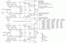
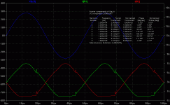
extremA output stage (simulations)
Ok, here the basic sim (no reactive parasitics).
Distortion values are "close to spectacular", at 20KHz full power (very close to A/B transition and reaching low Vce) only 50ppm, delivering 125W at 320W total power consumption.
Klaus
Ok, here the basic sim (no reactive parasitics).
Distortion values are "close to spectacular", at 20KHz full power (very close to A/B transition and reaching low Vce) only 50ppm, delivering 125W at 320W total power consumption.
Klaus
Attachments
Re: extremA output stage (simulations)
(cont'd)
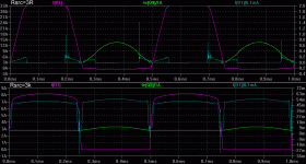
Overcurrent protection.
I found out what was wrong: I simmed with unlimited drive current, that defeated the limiter. I plotted current emitter currents of the output (R1), bias (Q9) and limiter (D1) trannys vs. source impedance (to mimick current limited drive) and then everything is OK.
- Klaus
Attachments
Klaus,
Those simulations look accurate, I see you use LTspice, as a coincidence I do too, very helpful piece of software if you ask me.
Cheers,
Sander Sassen
http://www.hardwareanalysis.com
Those simulations look accurate, I see you use LTspice, as a coincidence I do too, very helpful piece of software if you ask me.
Cheers,
Sander Sassen
http://www.hardwareanalysis.com
- Status
- This old topic is closed. If you want to reopen this topic, contact a moderator using the "Report Post" button.
- Home
- Amplifiers
- Solid State
- ExtremA, class-A strikes back?


