For good sound sufficient SR 1,6V/µs.
High audio frequency never have large amplitudes.
Plain nonsense.
I couldn't resist whipping up Pavel's idea in the simulator, made it into a full bridge for better efficiency and set the output for 80W/8R. The numbers I got aren't in the least bit disappointing, here's the THD20K at 80W/8R:
Fourier components of I(r38)
DC component:1.88071e-006
Harmonic Frequency Fourier Normalized Phase Normalized
Number [Hz] Component Component [degree] Phase [deg]
1 2.000e+04 3.171e+00 1.000e+00 -0.28° 0.00°
2 4.000e+04 3.375e-06 1.064e-06 -55.67° -55.39°
3 6.000e+04 5.025e-06 1.585e-06 -118.35° -118.07°
4 8.000e+04 2.325e-06 7.333e-07 157.09° 157.37°
5 1.000e+05 1.683e-06 5.308e-07 77.54° 77.82°
6 1.200e+05 9.958e-07 3.141e-07 0.57° 0.85°
7 1.400e+05 4.393e-07 1.386e-07 -107.32° -107.04°
8 1.600e+05 4.818e-07 1.520e-07 101.26° 101.54°
9 1.800e+05 8.989e-07 2.835e-07 7.13° 7.41°
Total Harmonic Distortion: 0.000216%(0.008551%)
Try to run asc file
http://www.diyaudio.com/forums/solid-state/96853-extrema-class-strikes-back-30.html#post4120514
Fourier components of I(r40)
DC component:0.000407211
Harmonic Frequency Fourier Normalized Phase Normalized
Number [Hz] Component Component [degree] Phase [deg]
1 1.000e+04 2.669e+00 1.000e+00 178.12° 0.00°
2 2.000e+04 5.812e-08 2.178e-08 3.00° -175.12°
3 3.000e+04 5.652e-06 2.118e-06 -124.58° -302.70°
4 4.000e+04 3.135e-08 1.174e-08 -0.20° -178.32°
5 5.000e+04 3.423e-07 1.282e-07 67.10° -111.03°
6 6.000e+04 2.038e-08 7.636e-09 0.03° -178.09°
7 7.000e+04 2.216e-08 8.303e-09 -60.47° -238.59°
8 8.000e+04 1.510e-08 5.659e-09 -0.11° -178.23°
9 9.000e+04 1.385e-08 5.188e-09 5.15° -172.97°
Total Harmonic Distortion: 0.000212%
Try to run asc file
http://www.diyaudio.com/forums/solid-state/96853-extrema-class-strikes-back-30.html#post4120514
Fourier components of I(r40)
DC component:0.000407211
Harmonic Frequency Fourier Normalized Phase Normalized
Number [Hz] Component Component [degree] Phase [deg]
1 1.000e+04 2.669e+00 1.000e+00 178.12° 0.00°
2 2.000e+04 5.812e-08 2.178e-08 3.00° -175.12°
3 3.000e+04 5.652e-06 2.118e-06 -124.58° -302.70°
4 4.000e+04 3.135e-08 1.174e-08 -0.20° -178.32°
5 5.000e+04 3.423e-07 1.282e-07 67.10° -111.03°
6 6.000e+04 2.038e-08 7.636e-09 0.03° -178.09°
7 7.000e+04 2.216e-08 8.303e-09 -60.47° -238.59°
8 8.000e+04 1.510e-08 5.659e-09 -0.11° -178.23°
9 9.000e+04 1.385e-08 5.188e-09 5.15° -172.97°
Total Harmonic Distortion: 0.000212%
Are you referring to the discrete design, or the opamp design? I'm assuming the former? In that case, .four 20k I(R40) is what you'd like to use.
SSassen,
Power supply can be lower (V2 and V3 = 18-20V).
Correct, with 20V per rail for the output stage there's a bit of headroom left still and efficiency goes up. Simulated efficiency is 152W in 80W out, which is 80/152 > 53%.
So try it, simply edit 10kHz to 20kHz...four 20k I(R40) is what you'd like to use.
Fourier components of I(r40)
DC component:0.000265904
Harmonic Frequency Fourier Normalized Phase Normalized
Number [Hz] Component Component [degree] Phase [deg]
1 2.000e+04 3.465e+00 1.000e+00 176.23° 0.00°
2 4.000e+04 8.835e-09 2.550e-09 28.75° -147.48°
3 6.000e+04 4.338e-06 1.252e-06 -138.55° -314.78°
4 8.000e+04 1.114e-08 3.216e-09 -8.34° -184.57°
5 1.000e+05 3.114e-06 8.989e-07 63.60° -112.63°
6 1.200e+05 5.183e-09 1.496e-09 -7.20° -183.43°
7 1.400e+05 3.595e-07 1.037e-07 -119.38° -295.61°
8 1.600e+05 3.816e-09 1.101e-09 -12.84° -189.07°
9 1.800e+05 4.946e-08 1.427e-08 61.28° -114.96°
Total Harmonic Distortion: 0.000154%
Last edited:
So try it, simply edit 10kHz to 20kHz..
I'm sorry, I'm not entirely sure what you'd like me to do? You also need to change the input to SINE(0 1.4 20k) if you want to look at THD@20K.
Sine source is defined this way, "SINE(0 1.3 {freq} 0 0 0 10)", and parameter {freq} is defined in schematic as spice directive line ".param Freq=20k". So it is enough to edit 10kHz to 20kHz in this line...
And .asc file is in post 298 .
I'm sorry, but I don't need tutoring on how to use LTspice

SSassen,
Power supply can be lower (V2 and V3 = 18-20V).
With 2 x 18V for the opamp, you need at least 2 x 22V for the output stage (ccs and triple junction margin), otherwise distortion gets higher).
Nice idea. Kinda reminds me of driving a OPS bias pair with ref to the output. Conceptually, wasnt that done in a former life with a diode-resistor from output to bias (spreader)? (NPass). But this is a nice balanced circuit refinement.... like a comparitor, too.
Opamp input now then one of the many good discrete front end, later?
THx-RNMarsh
Last edited:
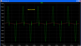
No load on the opamp is great as that was the last area of concern (OPS loading) for using opamps. How much current does the sim say the opamp must supply (max) when the amp goes out of class A?
THx-RNMarsh
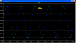
Not nice, then. Starts quite mild, as attached, but continues to milliamps and tens of milliamps.
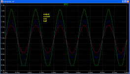
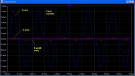
The image is for stepped load 8, 6, 4 ohms. You can see input current and ouput current through one output device.
added an image for 2 ohm load
Attachments
Last edited:
2 SSassen
So why You ask this?I'm sorry, but I don't need tutoring on how to use LTspice
I'm sorry, I'm not entirely sure what you'd like me to do? You also need to change the input to SINE(0 1.4 20k) if you want to look at THD@20K
How much is the (theoretical) maximal efficiency of this OPS?...Simulated efficiency is 152W in 80W out, which is 80/152 > 53%.
- Status
- This old topic is closed. If you want to reopen this topic, contact a moderator using the "Report Post" button.
- Home
- Amplifiers
- Solid State
- ExtremA, class-A strikes back?