MikeB said:BTW, it's a good idea to replace the 1k pot by a 470ohms one, the setting is anyway always far below 50%... That makes the adjusting easier.
Mike
Hi MikeB 🙂
Funny you mentionned this as I was in the process to select a 10 or 20 turns sealed pot from Bourns 😀
BTW what is the best way to adjust this pot ?
I do have few scopes (60, 400 & 500 MHz) precise DMM but no distortion analyser (yet).. I saw some software using your creative ZS PC sound card as distortion analyser.. Not sure if it's realistic or not.. 😕
Thank you anyway for your help, very much appreciated 😀
MikeB:
Please do put Gerber files on your web. Have PCBs made by pro-ship saved me drilling 340 some holes that I am really not looking forward to.
Henrik04:
What are the problems with the Excellon files? I used it to have PCBs made without problem. My Gerber viewer was not able to plot the holes properly, even though I was able to confirm the coordinates and hole sizes manually.
tttking said:MikeB:
Please do put Gerber files on your web. Have PCBs made by pro-ship saved me drilling 340 some holes that I am really not looking forward to.
Henrik04:
What are the problems with the Excellon files? I used it to have PCBs made without problem. My Gerber viewer was not able to plot the holes properly, even though I was able to confirm the coordinates and hole sizes manually.
Hi tttking 🙂 I'm at work now, (so I don't have details here) Gerbtools complained but accepted the coper and silkscreen. So I'll have a look at home and I'll let you know.
I think I did read that I should ajdjust the pot to get 6.6 mV across R27. Is this the right way to adjust the pot?
Thank you in advance.
Henri
 Sorry I asked.. I didn't read post 1562..
tttking said:henrik04:
Here are the Excellon drill files:
Please note I change the solder file for the component side slightly to cover up most parts of the pads.
Hi.. 🙂
The error reported by Gerbtools is D25 which is a size of 0. However it seems that everything else seems ok..
Cheers
Henri
tttking said:MikeB:
Please do put Gerber files on your web. Have PCBs made by pro-ship saved me drilling 340 some holes that I am really not looking forward to.
Hi Tim, just uploaded them... 🙂
Mike
In the same spirit
People are going to kill me but.. I tried to use available components but the silver mica caps I found did not fit at all the board. I found as well some non inductive resistor in TO220 for R1 and R3. (Named this way in 5_3). They are too far from the edge of the board. So I thought in the spirit of DIY to redraw the PCB and therefore update the schematic with the component I found.. Maybe some of you will be interested, maybe not.. 😀 As a first task, I did enter in my schematic package the parts, and I ran the automatic parts numbering.. Have a look, maybe I did an enormous mistake?
Please let me know..
Cheers
Henri
People are going to kill me but..
I tried to use available components but the silver mica caps I found did not fit at all the board. I found as well some non inductive resistor in TO220 for R1 and R3. (Named this way in 5_3). They are too far from the edge of the board. So I thought in the spirit of DIY to redraw the PCB and therefore update the schematic with the component I found.. Maybe some of you will be interested, maybe not.. 😀 As a first task, I did enter in my schematic package the parts, and I ran the automatic parts numbering.. Have a look, maybe I did an enormous mistake? Please let me know..
Cheers
Henri
Attachments
Hi Henrik !
I found some small mistakes...
C4/15 were intended to be 1000uF,C9 should be 10pF, in paralell to R15 you should have 100nf, and you should keep the REs for Q5/Q6, they are helpful when gain needs to be lowered. C10 can be 16v version. (much smaller case)
Thanks for doing that, i also realized that the mica-caps other builders use are much bigger than the ones i use...
Mike
SymaSym 5_4a
Thank you mikeB for taking the time to look at it. 🙂
I corrected my mistake and call the updated version 'a' to avoid confusing anyone following the thread.
I'm sorry but I don't understand the above statement.. 'res with Q5 and Q6'
Please can you tell me which resistor I didn't place ?
Thank you in advance.
Cheers
Henri
MikeB said:
you should keep the REs for Q5/Q6, they are helpful when gain needs to be lowered.
Mike
Thank you mikeB for taking the time to look at it. 🙂
I corrected my mistake and call the updated version 'a' to avoid confusing anyone following the thread.
I'm sorry but I don't understand the above statement.. 'res with Q5 and Q6'
Please can you tell me which resistor I didn't place ?
Thank you in advance.
Cheers
Henri
Attachments
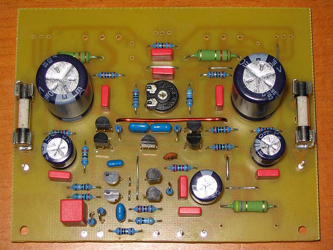
Emitter resistors. In emitters of Q5 and Q6. This resistors is not included on mikes schematic. But on mikes boards for 5_3 are place for them. Look between the fourth of TO-92 cases in lower left. There are two small links. There may be gain decreasing resistors.
Enjoy
Enjoy
Chuck911 said:Emitter resistors. In emitters of Q5 and Q6. This resistors is not included on mikes schematic. But on mikes boards for 5_3 are place for them. Look between the fourth of TO-92 cases in lower left. There are two small links. There may be gain decreasing resistors.
Enjoy
😀 Thank you for this Chuck911.
Enclosed is the updated schematic. I placed two little jumpers to short circuit Q5 and Q6 resistors. So it is easy to see the effect with and without the resistors.
Question:
What sort of capacitor for the 4.7 uF at the input? Before I start the PCB I need to know (and find) this device.
Thank you in advance. 🙂
Attachments
Polypropylene caps
Hi Chuck.🙂 I don't see any problem in using this serie of capacitors (MKP380 or 384S). The only thing, is the board will be larger. But for me this is not an issue. It was going to be larger anyway due to the fact that the two emiter resistor R13 and R17 are in a TO220 package anyway. Their web site is well documented. So let's go for this serie of caps..
mikeB: Do you see any other possible issue in using these? if so please let me know.
Cheers everyone 😀
Chuck911 said:mikeB used MKS for this device and for many other on board. IMHO this is not the best choice for audio. I want to use MKP. But there are not caps in needed cases. I want to choose something like this: MKP Caps
Hi Chuck.🙂 I don't see any problem in using this serie of capacitors (MKP380 or 384S). The only thing, is the board will be larger. But for me this is not an issue. It was going to be larger anyway due to the fact that the two emiter resistor R13 and R17 are in a TO220 package anyway. Their web site is well documented. So let's go for this serie of caps..
mikeB: Do you see any other possible issue in using these? if so please let me know.
Cheers everyone 😀
Hi I dont thing there is problem with cases of this MKP devices on mikes original 5_3 board. I will assebly them verticaly. And I have my boards made. They are on the way home 🙂 Profi double sided board with 105/105um copper ARGH...ARGH....ARGH 😀
Chuck911 said:Hi I dont thing there is problem with cases of this MKP devices on mikes original 5_3 board. I will assebly them verticaly. And I have my boards made. They are on the way home 🙂 Profi double sided board with 105/105um copper ARGH...ARGH....ARGH 😀
Very good 🙂 I never intended to make a single sided board anyway
 But I think placing all the components horizontally looks more professional. (just a tiny detail anyway).
Question: Do you know what is the minimum order quantity from ESO for these capacitors?
ESO Polypropylene capacitors
Because if they required 5000 pieces as a minimum order quantity it's not a good solution. Unless some distributors carry their product range.. 😕
Chuck911 said:For your question: I have absolutely no idea. Why?
Because if they required 5000 pieces as a minimum order quantity it's not a good solution. Unless some distributors carry their product range.. 😕
I´m studiing in Ostrava. I will go to their shop in factory area. People here tell me that they sell retail there.
- Home
- Amplifiers
- Solid State
- Explendid amplifier designed by Michael Bittner, our MikeB