J. Wright said:I am anxious to hear how this one sounds compared to the other. The folded cascode is faster. I don't see any compensation though. Have you ever considered using lateral mosfets as drivers. It elliminates a stage, and temperature compensates the outputs as well, if you choose the drain current carefully.
J.
Hi J. !
Yes, the folded cascode is faster, but the highgainversion sounded
better. The problem with the foldedcascode version was that because
of the low gain the tanh() nature of the 1st diffamp got dominant
in distortionfigures and created too much 3rd harmonic distortion.
This yielded in a unpleasant/unmusical sound.
If you take a close look, you will see plenty of compensation, i just
avoid using cdoms.
I don't have much experience with mosfets, i have not tried the
lateral mosfets yet. My experience with v-mosfets was not the best
regarding soundquality. (Have not tried with EC yet)
Mike
Moray, i was talking about AKSA 55, that amplifier came in many versions, at least
3 versions as i could see, and there are one version that you have the choice to colect the output very near the input, as the board provide, as option, the possibility to install a metalic post between the negative rail and ground star point.... not more than 20 milimeters distant from differential amplifiers.
Depending the way you assemble the output coil, that can be soldered under the board, connecting the output line to some input post, you can have some coupling from output to input,...that construction, if the constructor have not care to put the coil more distant, can produce some metalic treble, and in this case, is the magnetic coupling result as i could test here.
The result is more an effect than a defect, as produces a very interesting sound.
Normally, Aksa has magnificent trebles, unbeatable trebles i think, but bad construction uses, result of some no experienced customers, can create some problems.
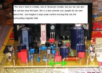
This coupling problem is very common, you can see close distance also in Symassym, and in many others.
If you assemble the coil, over the board and aerial, or following Hugh written instructions, the way is shown in the diagram, supplied, no problem, but I made my experiences, also i constructed other coil sizes and diameters, and discovered that many guys can put that coil wrong.
Threshold of oscilation, is because if you put this coil very near, almost touching the first differential amplifier, of course you will have oscilations, i have done it and could listen a broadcasting station that is 4 miles ahead, with 20 Kilowatts of power...enormous AM broadcasting station.
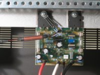
This clean assemble that you can see, was made by our forum friend Greg, from Australia, and the board model was 1.6, he used the output coil in aerial way...pretty construction, and beautifull board, all Hugh board are pieces of Art work.
regards,
Carlos
3 versions as i could see, and there are one version that you have the choice to colect the output very near the input, as the board provide, as option, the possibility to install a metalic post between the negative rail and ground star point.... not more than 20 milimeters distant from differential amplifiers.
Depending the way you assemble the output coil, that can be soldered under the board, connecting the output line to some input post, you can have some coupling from output to input,...that construction, if the constructor have not care to put the coil more distant, can produce some metalic treble, and in this case, is the magnetic coupling result as i could test here.
The result is more an effect than a defect, as produces a very interesting sound.
Normally, Aksa has magnificent trebles, unbeatable trebles i think, but bad construction uses, result of some no experienced customers, can create some problems.
This coupling problem is very common, you can see close distance also in Symassym, and in many others.
If you assemble the coil, over the board and aerial, or following Hugh written instructions, the way is shown in the diagram, supplied, no problem, but I made my experiences, also i constructed other coil sizes and diameters, and discovered that many guys can put that coil wrong.
Threshold of oscilation, is because if you put this coil very near, almost touching the first differential amplifier, of course you will have oscilations, i have done it and could listen a broadcasting station that is 4 miles ahead, with 20 Kilowatts of power...enormous AM broadcasting station.
This clean assemble that you can see, was made by our forum friend Greg, from Australia, and the board model was 1.6, he used the output coil in aerial way...pretty construction, and beautifull board, all Hugh board are pieces of Art work.
regards,
Carlos
Attachments

Hi Carlos !
I was aware of this problem with the magneticfield, but found no
better way to place this coil...
I had done it before, and observed no change in stability.
As the 2 transistors at input are very close, both get the same
signal inducted, so nothing can happen here. (In theory)
And... it's a very small coil...
Mike, now suddenly hungry !
Aaaagh!...no one can catch you...very intelligent Michael...you are really clever.
The induced magnetic field, as will cross both differential amplifiers will be cancelled...ahahahah..this was great.
But will apply a node on you...take a look in my example of magnetic propagation...can you see that the feedback transistor will receive the interference delayed related the input one?
Hummmm, you will say that the electrolitic will take care of that.
Yeah!...no chance, you win that one too..point for you.....aaaaagh!
regards,
Carlos
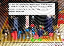
Hi Epupa, this is a Magnetronic picture taken from MikeB amplifier.
Having long time exposition, the waving was the magnetron effect, when 100 watts of 60 hertz tone was over 4 ohms load.
You can see the magnetic image, that Mike said that will not produce interference.
ahahaha!.... kidding guys, this is an picture effect of the ACDsee program...swivell is the name, i think.
But can have some idea of wave propagation from a target source.
regards Epupa...good to see you here with us.
This amplifier have quality, no one will lost time with it.
If not satisfied, can call me Charlotte (impossible, i have any fear)
- Mike, i am sorry...i am having wonderfull Strawberries with cream...rigth now..the problem is that more than 2 pounds are there....hehe...no one wants more Michael!
regards,
Carlos
Attachments

Oh!..now i get it... this is a sweet, covered with melted sugar...now i get it Epupa
"Palmiere" is the french name.... have this magnetic field shape, made with paste and covered with sugar that will melt when cooked.
I also love to cook Epupa, i love not only transistors, also Girls, cars, and to cook also.
Here is one link to you.
http://www.denning.org.uk/cooking/spaetzle/
Brazil continue pretty good to live in... and beautifull too, with freedom and peace...well, the Government are making some foolishes, but nothing that we cannot fix.
regards,
Carlos")
"Palmiere" is the french name.... have this magnetic field shape, made with paste and covered with sugar that will melt when cooked.
I also love to cook Epupa, i love not only transistors, also Girls, cars, and to cook also.
Here is one link to you.
http://www.denning.org.uk/cooking/spaetzle/
Brazil continue pretty good to live in... and beautifull too, with freedom and peace...well, the Government are making some foolishes, but nothing that we cannot fix.
regards,
Carlos
Attachments

Oooof ! 250watts into 8ohms ? Makes ~70v supplyvoltage !
This would need heavy changes to the circuit, i can't increase
dissipation in vas-devices that much, they already get very warm...
I could make a tripledarlingtonversion and replace the mpsa18 and
the bc546 with higher voltage types.
At these high voltages i need to reduce current in vas, or these
to92-devices overheat. Another option would be using mje340/350
for vas, but these behave very different...
(Would need new adjusting of feedbackcompensation)
Does anyone has adequate models for these ?
Mike
All rigth, with your suggestions can be made.
I am thinking to use 54 Volts, the one i used in the SC480, changing BC transistors for higher voltage units, those ones that can overheat will receive another one in parallell, to divide this increase of power and heat, retouching bias, and accepting 4 ohms as load.
Do you think that i will have problems using 54 Volts simetrical supply?
In this case, more than 200 RMS will be easy to achieve (4 ohms).
Do you like the "home fast solution"...the parallell transistor to VAS...matched ones?...or the capacitance added will create too much problems?
I intend to make this, but only if the idea of good and cheap power amplifier can be untouched...if i starts to need components replacement, the price will increase, and will be going out of the excelent solution you achieve, with small and low priced transistors.... This is the main "Goal" you made in your unit...nothing sophisticated, all parts very common, easy to find, and result excelent.
This extra power is needed, as i am thinking to produce a subwoofer using your amplifier.
I know that it can give us much better than only bass, but already have good units to treble and to voice.
regards,
Carlos
Paralelling vas-transistors might be difficult, because you can't match
transistors perfectly you need RE's to really make them share the
job. The problem is, if one is slightly warmer than the other, it has
lower vbe, getting more work than the other, getting even more
warm and... Poof !
Also characteristics change...
Do you have transistors with vce of 120volts ?
With 2n5401/5551 again no problem...
I will check what i can do for 54volts, can you mail me your parts ?
Mike
MPSA42 and MPSA92, BC639C and BC640C,
Drivers can be 2SA1837 and 2SC4793
Output can be 2SC2922 and 2SA1215
I can also remove some turns of my transformer...to reduce to 50 volts, this will be good to BC639C.
Also i have another supply with adjustment, simetrical, going from 12 volts to 64 volts, but 7 amps each rail only.
Do not ask me the MPSA92 price.... aaaagh!
By the way, if you have problems to put those transistors on your Orcad Simulator, to produce decent hi power schematic, you may call a Computer Programmer...he will help you..... hôhôhô..har har har!
regards,
Carlos
thank mikeb ! Wil i be success if i don't match 2 transistors of current mirror ?
Buying a lot of transistors and match them is hard to me .and i haven't digital VOM (volmeter ohm miliamperer )
mikeb ! your schematic is similar to michael chua 's schematic but it is not a problem !
http://www.ampslab.com/bi70mk2_schematics.htm
Is this amp better than symmetrical amp which you posted in this forum ? Do you prefer this amp ?
I still use a symmetrical amp . I still believe in " symmetrical slewrate " .
I simulated your schematic but i haven't model of MJL transistors . I often use D669/B649 for VAS . Your new schematic have less harmonics than my schematic .Perhaps you used a current mirror . And probadly current mirror for input stage is not good thing
Hi thanh !
It's enough to match the 2 transistors in currentmirror for vbe...
With bad match you risk getting high dc-offset.
Depending on manufacturer transistors have only slightly varying
vbes, the onsemi smallsignal-bjts i got show variations barely
measurable. That makes complementary matching impossible,
the mainreason why i said goodbye to symetrical circuits.
Because of the symetric nature of the vas in symasym, slewrate
is symetrical... I do not like currentmirror in inputstage much...
I know that the bi120 from ampslab is very similar, i never said
that i invented something new...
But i have a completely different parts-choice and feedbackcompensation.
For this circuit you should not replace the vas-transistors, the
sb649a has very different specs than 2n5401.
Mike
- Home
- Amplifiers
- Solid State
- Explendid amplifier designed by Michael Bittner, our MikeB